2 input signal arrangement – SHIMPO DEG-2000 User Manual
Page 22
20
7.3.2 Input signal arrangement
Note:
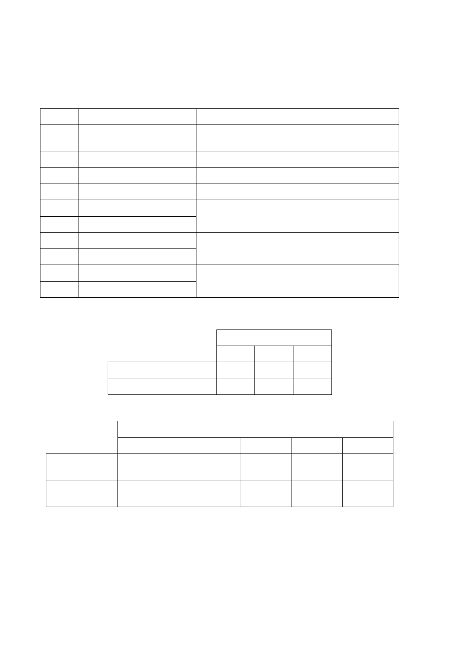
The input signals are enabled when “READY” is turned on. The following
table shows the input signal arrangement of the DC input/output connector
(refer to ◯
15
on page 7).
Pin No.
Signal name
Description
1
Measure command
Hold measured value and data output command
(Enabled when mastering result is OK.)
2
Minimum mastering
Minimum mastering command
3
Maximum mastering
Maximum mastering command
4
RESET
Measured value hold clear command
5
Program change (lower)
6
Program change (higher)
Specifies program numbers 1 to 3 to be changed.
(Refer to Table 6.)
7
Item bit (less significant)
8
Item bit (more significant)
Specifies measurement items 1 to 3 to be output.
(Refer to Table 7.)
9
+COM
10
+COM
Input common line: +12/24 V
Table 6. Program change and program numbers.
Program number
1
2
3
Program change (lower)
On
Off
On
Program change (higher)
Off
On
On
Table 7. Item bits and measurement items to be output.
Measurement item to be output
Setting for this instrument*
1
1
2
3
Item bit (less
significant)
Off
On
Off
On
Item bit (more
significant)
Off
Off
On
On
*
1
Item set with [JUDG OUT] is output.