KROHNE ALTOSONIC V Modbus EN User Manual
Page 11
ALTOSONIC V
ModBus Manual 0300 rev07 E
7.30855.35.00
Page 11 of 64
Note how the three remaining bits (toward the high order end) are zero-filled.
If the request is not applicable an exception response will be sent.
See chapter 5.10 for exception responses.
5.2
Function 02: READ INPUT STATUS
In the UFP-V Modbus protocol, function 1 and 2 perform the same processing and are
interchangeable.
5.3
Function 03: READ MULTIPLE HOLDING REGISTERS
Description
Function 3 reads the binary contents of holding registers (4X references) in the slave.
Broadcast is not supported.
The maximum number of registers at each request is limited to 125 registers, 125 integers, or 62 long
integers or 62 floats or 31 doubles.
Query
The query message specifies the starting register and the quantity of registers to be read. Registers
are addressed starting at zero. Registers 1-16 are addressed as 0-15.
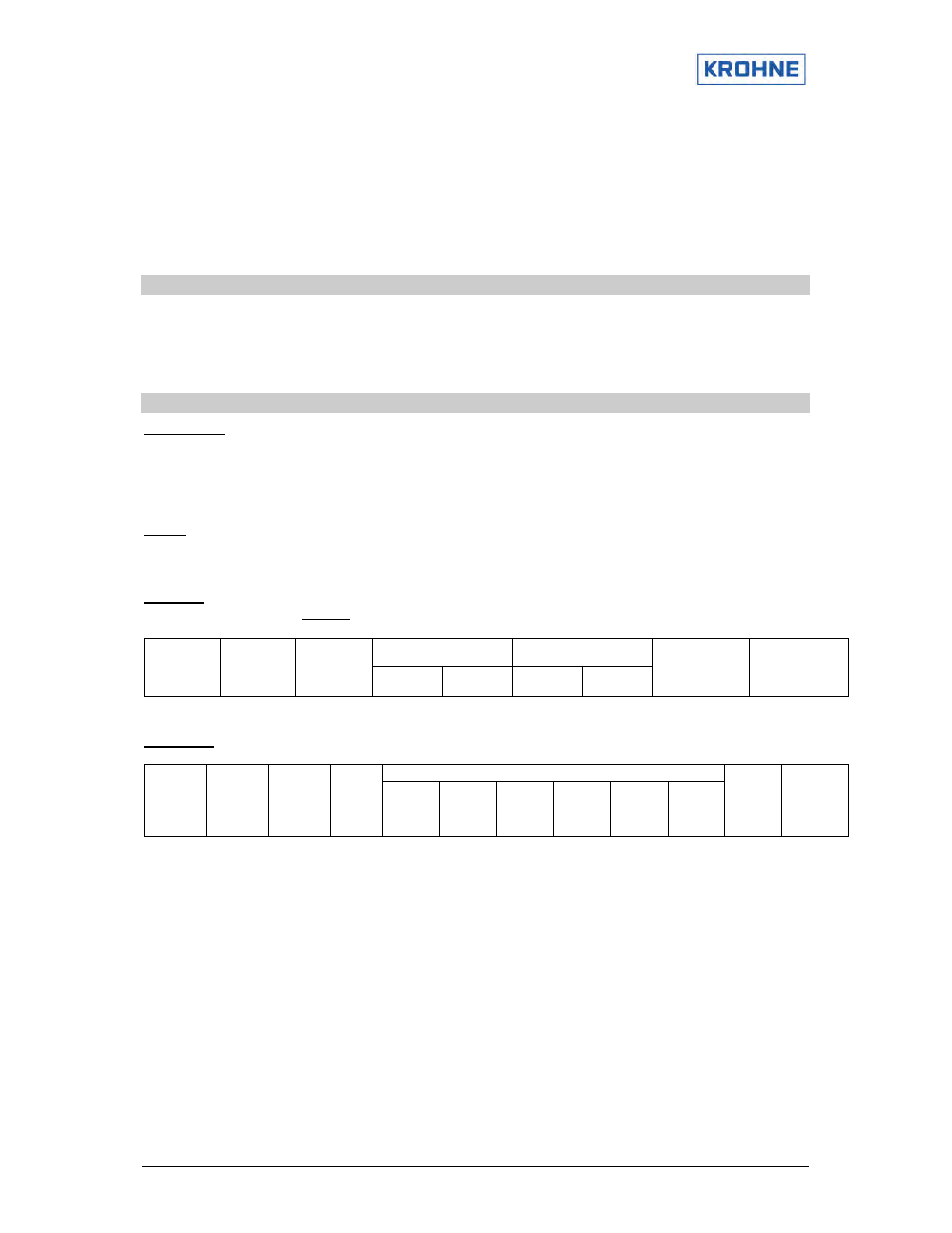
Example
Here is an example of a request to read registers 40108-40110 from slave device 17:
Starting address
Number of points
Header
--
Slave
Address
11(h)
Function
03(h)
Hi
00(h)
Low
6B(h)
Hi
00(h)
Low
03(h)
Error check
--
Trailer
--
Response
Data
Header
--
Slave
address
11(h)
Funct.
03(h)
Byte
count
06(h)
Reg.
40108
Hi
02(h)
Reg.
40108
Low
2B(h)
Reg.
40109
Hi
00(h)
Reg.
40109
Low
00(h)
Reg.
40110
Hi
00(h)
Reg.
40110
Low
64(h)
Error
check
--
Trailer
--
The register data in the response message are packed as two bytes per register, with the binary
contents right justified within each byte. For each register the first byte contains the high order byte, the
second the low order bits.
The contents of register 40108 are shown as the two byte values of 02 2B hex (555 decimal).
The contents of register 40109 are 00 00 hex and of register 40110 00 64 hex (100 decimal).
If the request is not applicable an exception response will be sent.
See chapter 5.10 for exception responses.