Operation – KROHNE OPTISYS SLM 2100 EN User Manual
Page 47
OPERATION
5
47
OPTISYS SLM 2100
www.krohne.com
03/2014 - 4002737302 - MA OPTISYS SLM 2100 R02 en
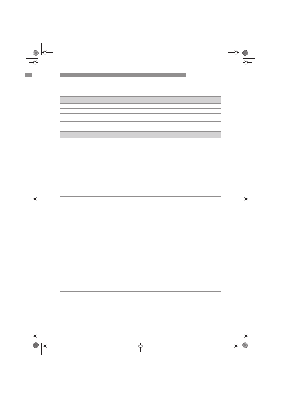
C2, maintenance
C3, I/O
Level
Designation / function
Settings / descriptions
This menu groups several other menus in which the maintenance functions can be set.
C2.1
Calibration
In this menu the concentration measurement can be calibrated. For further
information refer to
Calibration on page 55.
Level
Designation / function
Settings / descriptions
This menu groups several other menus in which the maintenance functions can be set.
C3.1
C3.1
C3.1
C3.1
Current out A
Settings of the corresponding current output.
C3.1.4
Error current
This function allows to define the current which indicates the error
condition.
Range: 3...22 mA (condition: outside of extended range)
C3.1.5
Error condition
This function allows to define which error categories will be indicated.
Options:
•
error in device: only errors of category F
F
F
F
•
application error: errors of category F
•
out of specification: errors of category S
C3.1.6
Time constant
Range: 0.1…100 seconds
C3.2
Current out B
Refer to submenus of current output A (all submenus and options are
identical, except that they start with C3.2).
C3.2.4
Concentration 4 mA
Definition of the sludge concentration at 4 mA (This menu is displayed only if
profile is selected in C3.1.1).
C3.2.5
Concentration 20 mA
Definition of the sludge concentration at 20 mA (This menu is displayed only
if profile is selected in C3.1.1).
C3.2.6
Error current
Definition of the current which indicates the error condition. Range: 3...22
mA (condition: outside of extended range)
C3.2.7
Error condition
This function allows defining the error categories will be indicated.
Options:
•
error in device: only errors of category F
F
F
F
•
application error: errors of category F
•
out of specification: errors of category S
C3.2.8
Time constant
Range: 0.1…100 seconds
C3.3
Control input 1
Settings of the corresponding control input
C3.3.1
Mode
This function allows to define the different modes of the corresponding
control input.
Options:
•
off
•
rake guard
•
trigger input
C3.3.2
Invert signal
This function allows to define how the control input is activated. Options: off
(control input is activated when the contact get closed at the input), on
(control input is activated when the contact is opened at the input).
C3.4
Control input 2
Refer to submenus of control input 1 (all submenus and options are
identical, except that they start with C3.4).
C3.4.1
Mode
This function allows to define the different modes of the corresponding
control input.
Options:
•
off
•
rake guard
•
trigger input
.book Page 47 Wednesday, April 30, 2014 1:39 PM