Operation, 5 menu mode structure – KROHNE OPTISYS SLM 2100 EN User Manual
Page 44
5
OPERATION
44
OPTISYS SLM 2100
www.krohne.com
03/2014 - 4002737302 - MA OPTISYS SLM 2100 R02 en
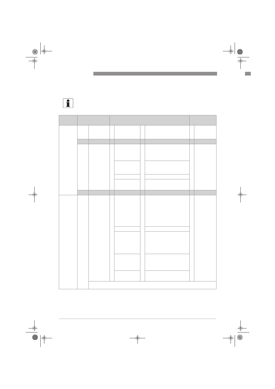
5.5 Menu mode structure
INFORMATION!
The following table just presents an overview. When programming the device, always consult the
function tables additionally as they contain further information!
Measuring
mode
Main menu
Submenu
Parameter
3 or 4
pages,
scrolling
with ↓ or ↑
> 2.5 s
^
A quick setup
A quick setup
A quick setup
A quick setup
>
^
A1 language
A2 set clock
A3 reset errors
>
^
For further
information
see function
tables.
↓↑
↓↑
↓↑
↓↑
> 2.5 s
^
B test
B test
B test
B test
>
^
B1 simulation
>
^
B1.1 current out A
B1.2 current out B
B1.3 relay 1
B1.4 relay 2
B1.5 cleaning
>
^
For further
information
see function
tables.
B2 actual values
B2.1 operating hours
B2.2 ADC value
B2.3 act. sensor temperature
B2.4 electr. temperature
B.3 logbooks
B3.1 status log
B4 information
B4.1 device serial number
B4.2 mainboard
B4.3 sensor electronic
↓↑
↓↑
↓↑
↓↑
3 or 4
pages,
scrolling
with ↓ or ↑
> 2.5 s
^
C setup
C setup
C setup
C setup
>
^
C1 measuring
>
^
C1.1 measuring function
C1.2 measuring mode
C1.3 definition fluff
C1.4 def. sludge blanket
C1.5 hysteresis
C1.6 tracking time
C1.7 tracking position
C1.8 start signal
C1.9 timer interval
C1.10 units
>
^
For further
information
see function
tables.
C2 maintenance
C2.1 calibration
C3 I/O
C3.1 current out A
C3.2 current out B
C3.3 control input 1
C3.4 control input 2
C3.5 control input 3
C3.6 relay 1
C3.7 relay 2
C4 extended
setup
C4.1 maximum depth
C4.2 start position
C4.3 blind zone
C4.4 rake height
C4.5 cleaning
C5 device
C5.1 device info
C5.2 display
C5.3 special functions
D service:
D service:
D service:
D service: This menu is password protected and contains functions to be used by service
personnel only.
.book Page 44 Wednesday, April 30, 2014 1:39 PM