Electrical connections – KROHNE OPTISYS SLM 2100 EN User Manual
Page 21
ELECTRICAL CONNECTIONS
4
21
OPTISYS SLM 2100
www.krohne.com
03/2014 - 4002737302 - MA OPTISYS SLM 2100 R02 en
Electrical connections
4.1 Safety instructions
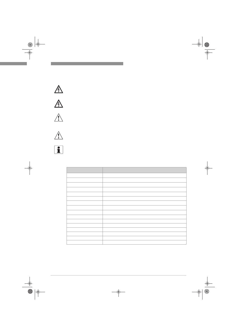
4.2 Used abbreviations
DANGER!
All work on the electrical connections may only be carried out with the power disconnected. Take
note of the voltage data on the nameplate!
DANGER!
Observe the national regulations for electrical installations!
WARNING!
Observe without fail the local occupational health and safety regulations. Any work done on the
electrical components of the measuring device may only be carried out by properly trained
specialists.
WARNING!
Before performing any work on the device switch off the power and make sure that it cannot be
switched on accidently.
INFORMATION!
Look at the device nameplate to ensure that the device is delivered according to your order.
Check for the correct supply voltage printed on the nameplate.
Abbreviation
Description
CI
a
Control input active
I
a
Current output active
I
max
Maximum current
I
nom
Nominal current
R
L
Load resistance
P
Power
U
int, nom
Nominal internal voltage
U
ext
External voltage
U
o
Terminal voltage
VAC
Volt alternated current
CI
Control input
PCS
Process control system
NO
Switch (normally open)
NC
Switch (normally closed)
LED
Light-emitting diode
K
Relay
.book Page 21 Wednesday, April 30, 2014 1:39 PM