Device description, 2 device description – KROHNE OPTISYS SLM 2100 EN User Manual
Page 11
DEVICE DESCRIPTION
2
11
OPTISYS SLM 2100
www.krohne.com
03/2014 - 4002737302 - MA OPTISYS SLM 2100 R02 en
2.2 Device description
Main electronics unit
The main electronics unit is located in a separate compartment above the cable drum, which can
be accessed via a separate door with a key lock. It contains the main board and fan assembly.
The main board bears the main processor and all electrical connectors. It also controls all
mechanical and electrical events in the device and communicates with sensor, display and
keyboard. It additionally contains the current outputs and control inputs.
Fan assembly
The position of the fan is on the top right side of the enclosure. Together with the heater it
maintains a stable temperature inside the enclosure of the meter.
Display and keyboard
Display and keyboard are located in the front door of the electronics compartment. Display and
keyboard are based on the GDC (general device concept), which means a common HMI to all
KROHNE GDC instruments is provided. The keyboard consists of four membrane keys and the
display is a LCD graphic display with a resolution of 128 x 64 Pixel.
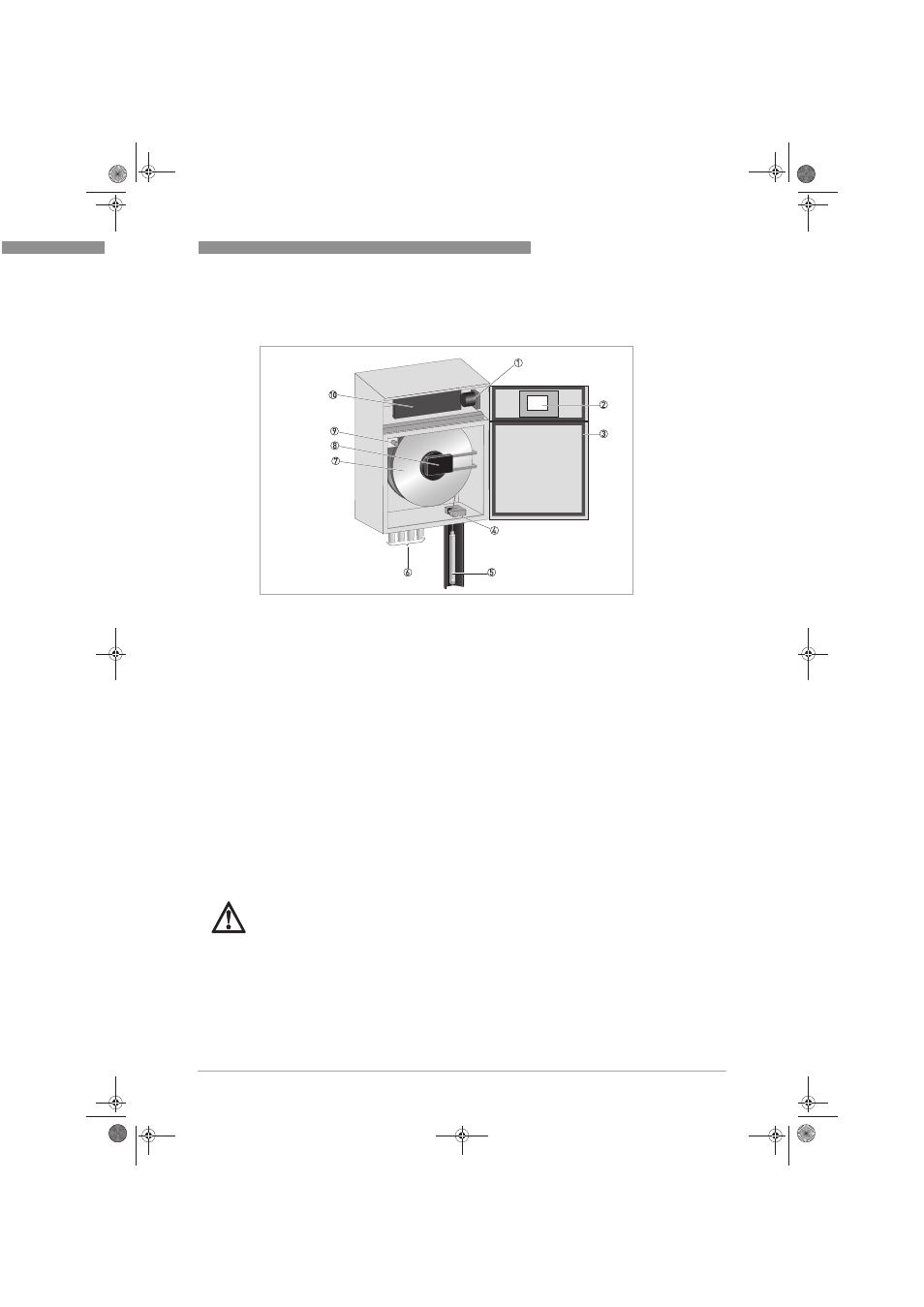
Figure 2-2: Device description of OPTISYS SLM 2100
1 Fan
2 Electronic compartment door with display
3 Cable drum compartment door
4 Guide roller
5 Sensor
6 4 x cable feedthrough M20
7 Cable drum
8 Pickup and axle board with optical interface
9 Safety switch
10 Main electronics and connectors
DANGER!
The rotating fan blades can be accessed, when the electronic compartment door is open and
there is a risk of injury when rotating fan is touched.
.book Page 11 Wednesday, April 30, 2014 1:39 PM