Electrical connections – KROHNE OPTISYS SLM 2100 EN User Manual
Page 34
4
ELECTRICAL CONNECTIONS
34
OPTISYS SLM 2100
www.krohne.com
03/2014 - 4002737302 - MA OPTISYS SLM 2100 R02 en
Note the electrical properties of the relays. For more information refer to
Technical data on page
68.
The terminals for the connection of the two current relays are located on the main board. Please
refer to the following diagram for proper connection of the cables.
The electrical specifications of the relays (K1 and K2) are as follows:
U
ext
≤ 24 VDC/250 VAC (K2)
I ≤ 0.3 A (K3)
For installation of the relays follow the steps below:
• Move the sensor by using the manual operation in the home position and turn off the power of
the instrument.
• Open the cable drum and electronics compartment doors.
• Push the prepared cables through the cable feed through and route them to the electronic
compartment.
• Connect the positive and negative lead according to the connection diagrams above.
• Connect the shield to one side only e.g. on PCS (process control system) side.
• Tighten the screw connection of the cable entries securely.
• Seal all cable entries that are not needed with a plug.
• Close both compartment doors.
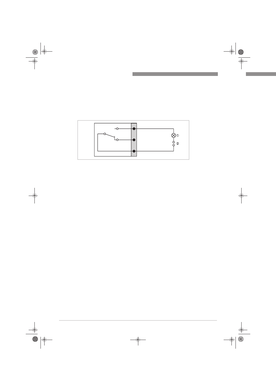
Figure 4-8: Connection diagram of relays K1 and K2
1 LED
2 Voltage source
.book Page 34 Wednesday, April 30, 2014 1:39 PM