Operation, 6 function tables – KROHNE OPTISYS SLM 2100 EN User Manual
Page 45
OPERATION
5
45
OPTISYS SLM 2100
www.krohne.com
03/2014 - 4002737302 - MA OPTISYS SLM 2100 R02 en
5.6 Function tables
5.6.1 Menu A, quick setup
A1, language
A2, set clock
A3, reset errors
5.6.2 Menu B, test
The procedure to start the simulation process is the same for all functions:
• Choose the function with the help of ↓ or ↑ and press ^.
i
You see the two options set value
set value
set value
set value (opens the editor to enter the simulation value) and break
break
break
break
(exit the menu without simulation).
• Choose the desired option with the help of ↑ or ↓ and press ^.
i
If you choose break
break
break
break you will exit the menu without simulation. If you chose set value
set value
set value
set value, the
device asks start simulation
start simulation
start simulation
start simulation and offers the options no
no
no
no (exit the menu without simulation) or
yes
yes
yes
yes (starts the simulation finally).
• Choose the desired option with the help of ↑ or ↓ and press ^.
i
If you choose yes
yes
yes
yes, the simulation starts. If you choose no
no
no
no, you will exit the menu without
simulation.
B1, Simulation
B2, actual values
Language selection (depends on the region for which the device has been ordered). Available languages: German,
English.
Manual setting of date and time.
This functions allows to reset all errors that are not reset automatically (e.g. power fail or counter overflow). You can
answer the question "reset?" with the following options: no (exit without reset) / yes (reset and exit the function).
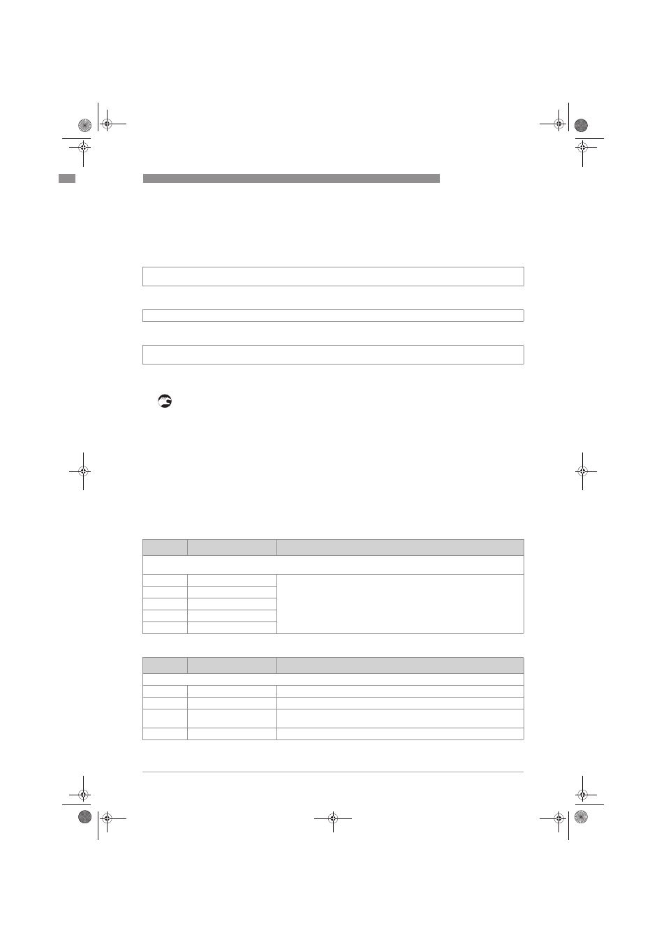
Level
Designation / function
Settings / descriptions
This menu groups several functions to simulate the input and output values. The procedure to start the simulation
process is the same for all function.
B1.1
B1.1
B1.1
B1.1
Current out A
Allows simulation of the corresponding output value.
B1.2
B1.2
B1.2
B1.2
Current out B
B1.3
B1.3
B1.3
B1.3
Relay 1
B1.4
B1.4
B1.4
B1.4
Relay 2
B1.5
B1.5
B1.5
B1.5
Cleaning
Level
Designation / function
Settings / descriptions
This menu groups several functions which allow to display the corresponding actual reading.
B2.1
B2.1
B2.1
B2.1
Operating hours
This menu shows the operating time of the devices in hours.
B2.2
B2.2
B2.2
B2.2
ADC value
This menu shows the raw ADC value of the sensor.
B2.3
B2.3
B2.3
B2.3
Actual sensor
temperature
This menu shows the actual temperature of the sensor.
B2.4
B2.4
B2.4
B2.4
Electronic temperature
This menu shows the actual temperature of the main board.
.book Page 45 Wednesday, April 30, 2014 1:39 PM