Figure 3-6. damping waveforms, 15 analog programming, Analog programming -21 – KEPCO EL Series Electronic Load Operator Manual P/N 243-1295 Firmware Version 3.63 through 3.86 User Manual
Page 57: Damping waveforms -21
SERIES EL 070312
3-21
• Twist the positive and negative cables together to provide as much cancelation of induc-
tance as possible.
• When using batteries, ensure they are fully charged when possible. Many styles of bat-
teries (especially lead-acid batteries) have a tendency to oscillate when excited by fast
rise-time transients. The sudden change in current causes the battery plates to warp
slightly, thus changing capacitance which interacts with the inductance of the cables.
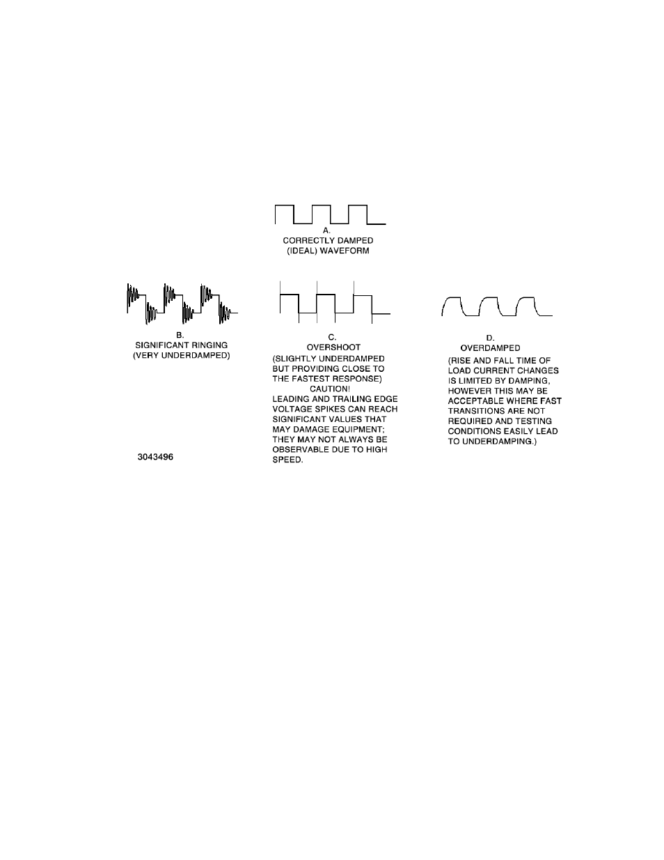
FIGURE 3-6. DAMPING WAVEFORMS
3.15
ANALOG PROGRAMMING
The Analog PGM input is summed with the digital setpoint value. Applying a positive voltage to
the Analog PGM input increases the digitally determined setpoint, and applying a negative volt-
age to the Analog PGM input decreases the digitally determined setpoint.
Because the analog signal is summed with the digital setpoint, it must produce a result that is
either 0 or positive, since the load can not control current in the negative direction.
For example, for the EL 5K-400-400 in CI Mode, if the digital setpoint is zero, a 0 to10V signal
applied to the PGM input adjusts the controlled parameter (current) from 0 to full scale (400A).
However, if the digital setpoint is set to 200A, ±5V applied to the Analog PGM input allows cur-
rent from 0A (-5V) to 400A (+5V).
The effect of the analog signal varies depending on mode selected (limited to CI, CP or CV) and
the range (see Table 3-3).
For Master/Slave configurations, the analog programming signal must be simultaneously
applied to all parallel-connected units.