Figure 2-9. typical master/slave interconnections, 4 analog control connections, Analog control connections -12 – KEPCO EL Series Electronic Load Operator Manual P/N 243-1295 Firmware Version 3.63 through 3.86 User Manual
Page 30: Typical master/slave interconnections -12, 4 for, E 2-9)
2-12
SERIES EL 070312
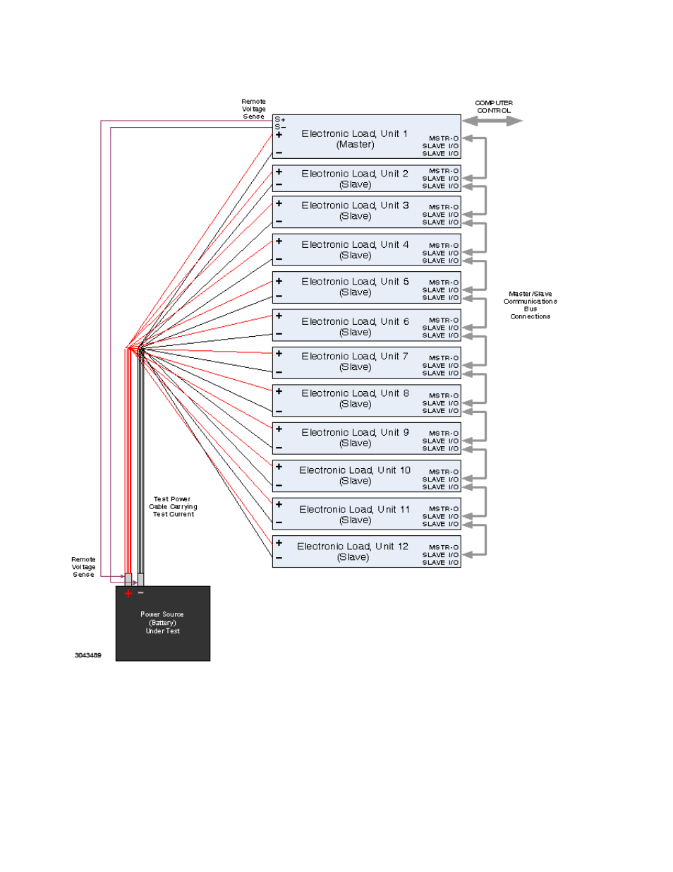
FIGURE 2-9. TYPICAL MASTER/SLAVE INTERCONNECTIONS
2.6.4
ANALOG CONTROL CONNECTIONS
The signal at the ANALOG CONTROL - PGM BNC connector (see Figure 2-3) is used for
remote analog programming of the load. For dual channel models (D suffix) this signal appears
at Pin 3 (pin 13 return) of the ANALOG CONTROL connector (see Figure 2-4). (NOTE: This sig-
nal is not provided on Model EL 3K-25-400DG). Applying 0 to10V adjusts the controlled param-
NOTES:
1 Remove local sense jumpers between + and S+ and between – and S– on
Master only. (See Fig. 2-8.)
2. Connect all Electronic Loads to Earth (safety) Ground using ground stud with
wingnut at upper left corner of each rear panel.
See also other documents in the category KEPCO Power suppliers:
- ABC-DM SERIES (96 pages)
- ATE (all models) QUICK START GUIDE (8 pages)
- SN 488-D (16 pages)
- SN 488-D (94 pages)
- SN 488-D (14 pages)
- BHK-MG 200W (Full Rack) Series (152 pages)
- BHK-MG 40W (Half Rack) Series (148 pages)
- BIT 232 (72 pages)
- BIT 4882 (56 pages)
- BIT 4886 Quick Start Guide (4 pages)
- BIT 4886 Operator Manual (92 pages)
- BOP 100W, 200W, 400W (M, D) Quick Start Guide (8 pages)
- BOP 20-5ML Modification Sheet (1 page)
- BOP 20-10MC Modification Sheet (2 pages)
- BOP 36-6MC Modification Sheet (2 pages)
- BOP 100-2MC Modification Sheet (2 pages)
- BOP 50-4MC Modification Sheet (2 pages)
- BOP 100-2ML Modification Sheet (2 pages)
- BOP 72-3ML Modification Sheet (2 pages)
- BOP 50-4ML Modification Sheet (2 pages)
- BOP 36-6ML Modification Sheet (2 pages)
- BOP 20-10ML Modification Sheet (2 pages)
- BOP 72-6MC Modification Sheet (2 pages)
- BOP 36-12MC Modification Sheet (2 pages)
- BOP 20-20MC Modification Sheet (2 pages)
- BOP 100-4ML Modification Sheet (2 pages)
- BOP 72-6ML Modification Sheet (2 pages)
- BOP 50-8ML Modification Sheet (2 pages)
- BOP 36-12ML Modification Sheet (2 pages)
- BOP 20-20ML Modification Sheet (2 pages)
- BOP 1KW-MG Quick Start Guide (16 pages)
- BOP 1KW-MG Quick Reference Guide (2 pages)
- BOP 1KW-MG Operator Manual, Firmware Ver.4.12 and higher (196 pages)
- BOP 1KW-MG Operator Manual, Firmware Ver.4.08 to 4.11 (194 pages)
- BOP 1KW-MG Operator Manual, Firmware Ver.3.05 to 4.07 (194 pages)
- BOP 1KW-MG Operator Manual, Firmware Ver.2.48 to 3.04 (188 pages)
- BOP 1KW-MG Operator Manual, Firmware Ver.2.38 to 2.47 (188 pages)
- BOP 1KW-MG Operator Manual, Firmware Ver.2.01 to 2.37 (176 pages)
- BOP 1KW as Solar Device Tester Quick Start Guide (3 pages)
- BOP-GL 1KW Quick Start Guide (16 pages)
- BOP-GL 1KW Operator Manual Firmware Ver.3.05 and higher (168 pages)
- BOP-HV (48 pages)
- CA 26 (2 pages)
- CA 27 (2 pages)
- CA 29 (2 pages)