Table 2-2. rear panel connections, 3 mains power requirements, Mains power requirements -5 – KEPCO EL Series Electronic Load Operator Manual P/N 243-1295 Firmware Version 3.63 through 3.86 User Manual
Page 23: Rear panel connections -5, E 2-2 pr
SERIES EL 070312
2-5
2.3
MAINS POWER REQUIREMENTS
The Electronic Load is delivered configured for operation from 120V a-c ±10%, 50/60 Hz. If the
load is to be operated from a 240V a-c ±10%, 50/60 Hz power source, or the input power range
needs to be changed from a previous selection, see PAR 2.3.1 to change mains power
CAUTION: The Series EL electronic loads do not have 120/240V automatic line voltage
switching. Applying 240V a-c to a load configured for 120V a-c will damage
the load.
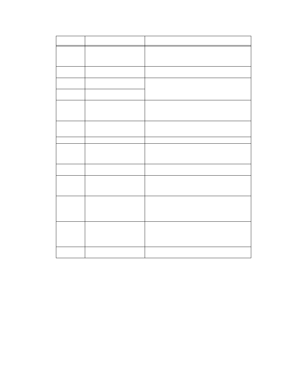
TABLE 2-2. REAR PANEL CONNECTIONS
FIG. 2-3 or 2-4
INDEX NO.
NAME
DESCRIPTION
1
120VAC 50/60HZ/
250VAC 50/60HZ/
POWER: IEC 60320-C13 line cord connector to connect
mains power (either 120 VAC 50/60 Hz or optional 240V AC
50/60 Hz). NOTE: changing mains power voltage requires
internal connector changes (see PAR. 2.3.1).
2
FUSE
FUSE: 120 V, 3AG, 3 Ampere Slo Blow (or 240V, 3AG, 1.5
Ampere Slo Blow)
3
LOAD (–)
Bus bar
UUT Connections. (–) Negative and (+) Positive: High cur-
rent connections to UUT. Connections to ±LOAD are typically
made using the supplied 3/8” low-resistance hardware (2
sets: bolt, nut and lockwasher).
4
LOAD (+)
Bus bar
5
SENSE
terminals
+S and –S terminals used for remote sensing. Install Jump-
ers between – and -S and between + and +S for local sens-
ing. Either local or remote sensing must be connected for
unit to operate. See 2.6.2.2 for details.
6
ANALOG
CONTROL
DB 15 Connector
Analog programming connections. Used for analog program-
ming input/output signals. See 2.6.4 for details.
7
LAN
Optional Ethernet connector.
8
MSTR (MSTR-O on D models)
Master Out
connector
Standard RS-522 connector. Connects from Master Out to
Slave In (SL-I or SL I/O) for multiple units in parallel (see Fig-
ure 2-9). See PAR. 3.16 for master/slave configurations. See
Table 1-5 to order RJ 22 master/slave cable.
9
RS-232
connector
Standard RS-232. Connects with a remote device using RS
232 protocols and SCPI commands (see Figure 2-3).
10
USB
connector
Connection to remote device for command, monitoring or
calibration. Use USB connector of master to communicate
with multiple loads in a master/slave configuration. (see Fig-
ure 2-7).
11
SL-I (SL I/O on D models)
Slave In/Out
connector
Standard RS-522 connector. Connects Slave to next slave
SL-O to SL-I (SL I/O to SL I/O on D models) if unit is a slave
in a parallel configuration using more than two units. Only
use Kepco cable (see Table 1-5) for master/slave connec-
tions (Figure 2-9).
12
SL-O (SL I/O on D models)
Slave In/Out
connector
Standard RS-522 connector. Connects Slave to next slave
SL-O to SL-I (SL I/O to SL I/O on D models) if unit is a slave
in a parallel configuration using more than two units. Only
use Kepco cable (see Table 1-5) for master/slave connec-
tions (Figure 2-9).
13
GPIB
IEEE 488 connector
Optional. When installed, connects user GPIB card with EL
load using standard GPIB cable (not supplied).