GW Instek GOS-6000 Series User Manual
Page 24
GOS-6051/6050/6031/6030 OSCILLOSCOPE
USER MANUAL
⎯ 42 ⎯
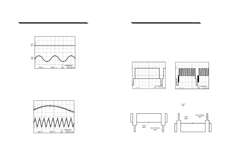
The VERT-MODE triggering is not possible when the signal is applied only to
one channel as shown in Figure 5-12 below:
Figure 5-12 Trig. Source on VERT. one channel
ALTERNATE TRIGGER
The Jittering wave as shown in Figure may appear on the screen when a gently-
slopping signal is displayed 10 cycles or less approximately by setting VERT-
MODE to SOURCE, and setting ALT/CHOP pushbutton to ALT. For detailed and
clear observation of each signal, set VERTICAL mode to CH1 or CH2.
Figure 5-13 Alternate Trig.
GOS-6051/6050/6031/6030 OSCILLOSCOPE
USER MANUAL
⎯ 43 ⎯
Triggering of Video signal
In the work concerned with TV, complex signals and containing video signal,
blanking pedestal signal, and synchronizing signal are often measured.
Press the TV pushbutton to set the TV position. The built-in active TV-Sync-
separator provides the separation of frame or line sync pulses from the video signal.
To trigger the oscilloscope at the vertical (frame) rate, press the TV pushbutton to
set TV-V and TV-H triggering. The figure 5-14(a) shows vertical signal of TV-V
and Figure 5-14(b) shows horizontal signal of TV-H.
Figure 5-14(a) TV-V
Figure 5-14(b) TV-H
The figure 5-15 shows the examples of TV polarity synchronization signals.
Note: This oscilloscope synchronizes with only ( ) synchronizing signal.
REFERENCE:
Figure 5-15 TV Signal