GW Instek GOS-6000 Series User Manual
Page 19
GOS-6051/6050/6031/6030 OSCILLOSCOPE
USER MANUAL
⎯ 32 ⎯
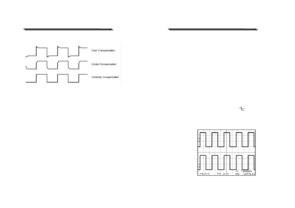
shown in figure 5-2. If either probe needs to be adjusted, proceed the step 8.
If either probe does not need to be adjusted, proceed the “Function Check”.
Figure 5-2 Typical Compensation Waveform
8.Adjust the probe by using a small insulated screwdriver. Slowly rotate the
adjustment control until the probe is properly compensated.
GOS-6051/6050/6031/6030 OSCILLOSCOPE
USER MANUAL
⎯ 33 ⎯
5-4.Function Check
When you start to check the operation of your oscilloscope, proceed the
following instruction:
1. Install the ×10 probes onto CH1 and CH2 inputs.
2. Connect the probe tips to the CAL test point of the oscilloscope.
3. Set the oscilloscope controls to display both channels:
VERTICAL:
VOLTS/DIV
0.2V
COUPLING
DC
ALT/CHOP
CHOP
HORIZONTAL:
TIME/DIV
0.5ms
TRIGGER:
MODE
ATO
SOURCE
VERT
COUPLING
AC
SLOPE
The figure 5-3 below illustrates a satisfactory display. The waveform should
be approximately 0.5Vp-p at a frequency of 1kHz that confirms the vertical
and horizontal deflection function of the oscilloscope.
Figure 5-3
- GDB-03 (99 pages)
- GLA-1000 Series User Manual (111 pages)
- GLA-1000 Series Quick start guide (20 pages)
- GOS-630FC (20 pages)
- GOS-635G (36 pages)
- GOS-6103C (30 pages)
- GOS-6100 Series (30 pages)
- GRS-6000A Series (51 pages)
- GDS-122 Installation Guide (4 pages)
- GDS-122 User Manual (52 pages)
- GDS-2000A series CAN/LIN bus User Manual (18 pages)
- GDS-2000A series Quick start guide for DS2-FGN (6 pages)
- GDS-2000A series Freewave User Manual (26 pages)
- GDS-2000A series Quick start guide for Logic analyzer option (18 pages)
- GDS-2000A series Quick start quide for DS2-LAN (2 pages)
- GDS-2000A series Option User Manual (80 pages)
- GDS-2000A series User Manual (261 pages)
- GDS-2000A series Programming Manual (272 pages)
- GDS-2000A series Single sheet for LA Quick start guide (2 pages)
- GBS-1000 Series Programming Manual (88 pages)
- GBS-1000 Series User Manual (187 pages)
- GDS-1000-U Series firmware upgrade (1 page)
- GDS-1000-U Series Programming Manual (70 pages)
- GDS-1000-U Series Quick start guide (2 pages)
- GDS-1000-U Series User Manual (133 pages)
- GDS-1000A-U Series Programming Manual (88 pages)
- GDS-1000A-U Series Quick start guide (2 pages)
- GDS-1000A-U Series User Manual (148 pages)
- GDS-3000 Series GCP-530/1030 current probe User Manual (40 pages)
- GDS-3000 Series GDP-025/050/100 differential probe User Manual (21 pages)
- GDS-3000 Series DS3-PWR Power analysis manual (37 pages)
- GDS-3000 Series User Manual (209 pages)
- GDS-3000 Series Programming Manual (103 pages)
- GDS-3000 Series DS3-SBD Serial Bus decode (29 pages)
- GDS-3000 Series GKT-100 deskew fixture User Manual (1 page)
- GDS-3000 Series GUG-001, GPIB to USB adapter User Manual (15 pages)
- GDS-300 Series User Manual (188 pages)
- GDS-300 Series Programming Manual (139 pages)
- GDS-300 Series Quick start guide (21 pages)
- GRF-3300 Series Student Manual (26 pages)
- GRF-3300 Series Teacher Manual (26 pages)
- GRF-1300A (124 pages)
- GSP-810 User Manual (40 pages)
- GSP-810 Software Manual (3 pages)