GW Instek GOS-6000 Series User Manual
Page 12
GOS-6051/6050/6031/6030 OSCILLOSCOPE
USER MANUAL
⎯ 18 ⎯
(23)CH1-X—Input BNC socket
This BNC socket is the signal input for channel 1. In X-Y mode, signals at
this input are used for the X deflection. The outer (ground) connection is
galvanically connected to the instrument ground and consequently to the
safety earth contact of the line/mains plug.
(24)CH2-Y—Input BNC socket
This BNC socket is the signal input for channel 2. In X-Y mode, signals at
this input are used for the Y deflection. The outer (ground) connection is
galvanically connected to the instrument ground and consequently to the
safety earth contact of the line/mains plug.
Horizontal controls:
The horizontal controls select the time base operation mode and adjust the horizontal
scale, position and magnification of the signal.
GOS-6051/6050/6031/6030 OSCILLOSCOPE
USER MANUAL
⎯ 19 ⎯
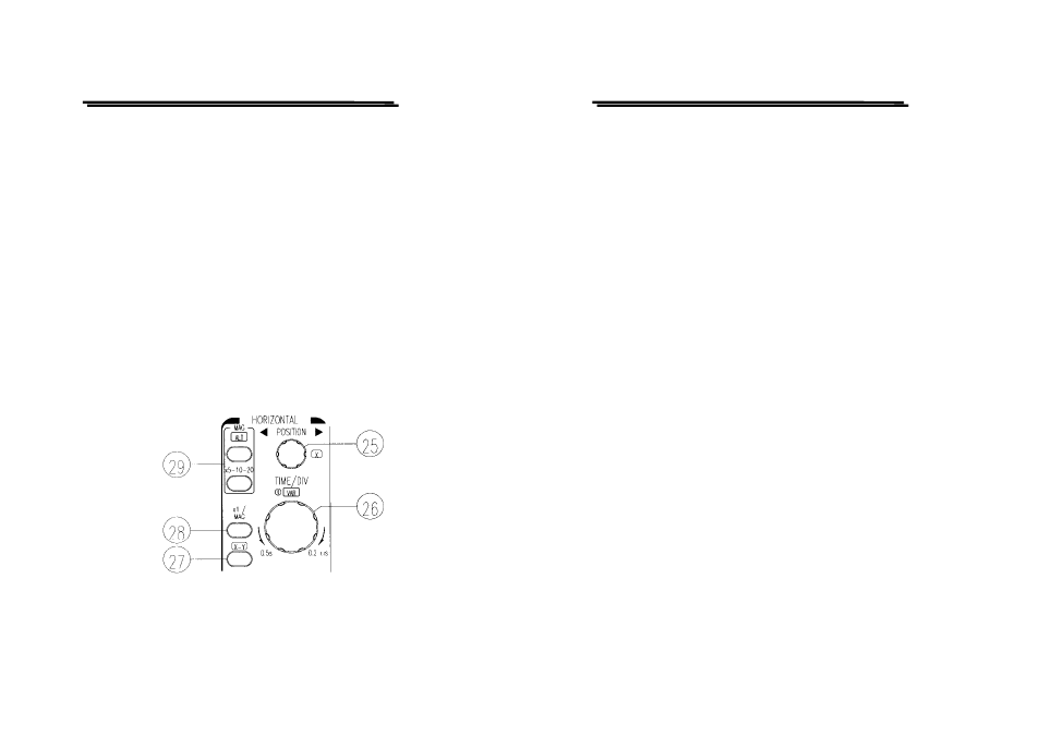
(25)H POSITION
The control knob enables a horizontal position shift of the signals. In
combination with MAG the function makes it possible to shift any part of
the signal on the screen.
In X-Y mode, the control knob are used for the X deflection.
(26)TIME/DIV-VAR– Control knobs
Turning the knob clockwise to reduce the deflection coefficient in a 1-2-5
sequence and turning it in the opposite direction (CCW) to increase. The
time coefficient(s) will be displayed in the readout.
The time deflection coefficients between 0.5s/div and 0.2μs/div can be
chosen in 1-2-5 sequence, if the MAG function is not activated.
VAR
Pressing the pushbutton to select the TIME/DIV control knob function
between time base switch and vernier (variable). After switching on the
VAR, the time deflection coefficient is still calibrated until further
adjustments are made. Turn the TIME/DIV control knob counter clockwise
to increase the time deflection coefficient (reduce the deflection speed) and
the deflection coefficient becomes uncalibrated. The current setting is
displayed by the “>” symbol in the readout.
(27)X-Y
Pressing the pushbutton when using the instrument as an X-Y oscilloscope.
The time deflection coefficient is replaced by the “X-Y” symbol in the
readout.
In this mode, the X (horizontal) signal is connected to the input of CH1;
the Y (vertical) signal is applied to the input of CH2 and has a deflection
range from less than 1mV to 20V/div at a reduced band-width of 500kHz.