Fire-Lite 411UDAC Fire Alarm Communicator User Manual
Page 23
411UDAC Manual — P/N 51073:E 9/20/2013
23
Input Channels
Installation
The channel/inputs may be programmed as shown below:
A maximum of five waterflow devices may be used on any circuit programmed as a waterflow zone
per NFPA 72.
It is allowable to mix an assortment of device types (i.e. smoke detectors, heat detectors, pull sta-
tions, etc.) on any zone. This is not recommended, however, since specific and detailed reports will
not be possible (particularly critical when using Contact ID format). For example, the report of
general fire alarm versus pull station fire alarm or smoke detector fire alarm could not be distin-
guished.
The factory default programming for each channel is as follows:
Channel 1 - fire alarm (4-wire smoke)
Channel 2 - pull station
Channel 3 - fire alarm (4-wire smoke)
Channel 4 - pull station
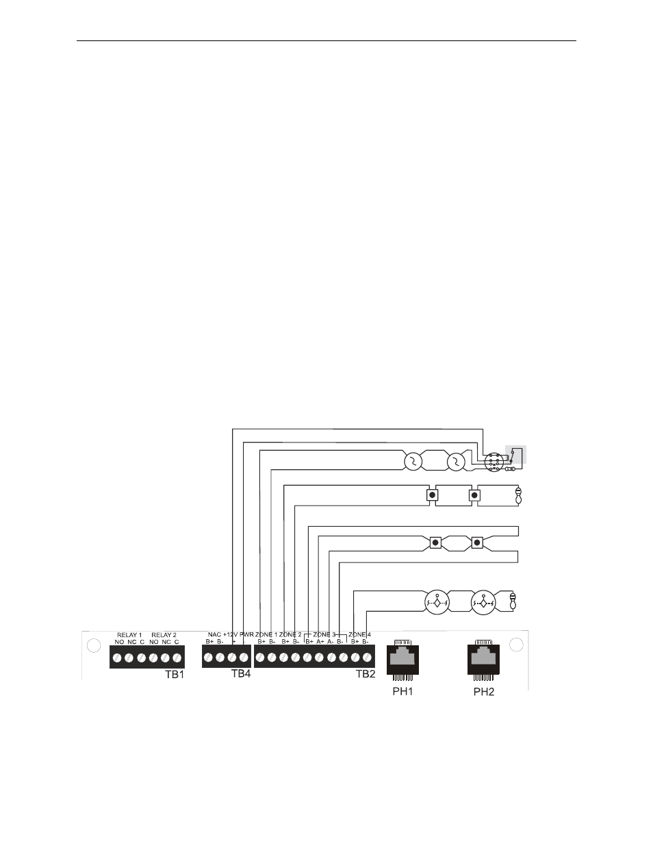
The following illustration shows Channel 1 connected to 4-wire smoke detectors, and UL-listed
power supervision relay; Channel 2 connected to manual pull stations; Channel 3 connected to
manual pull stations; and Channel 4 connected to waterflow devices. In this example, the factory
default programming for Channel 4 must be changed from pull station to waterflow device.
• 4-wire smoke detector (inputs 1 & 3 only)
• Supervisory
• Pull station
• Supervisory autoresettable
• Normally-open contact device
• Waterflow silenceable
• Host panel trouble
• Waterflow nonsilenceable
UL-listed
power
supervision
relay*
Manual Pull
Stations
(Class A)
Manual Pull
Stations
(Class B)
Waterflow
Devices
(Class B)
411UDAC Main Circuit Board
Zone 1/Channel 1
Zone 2/Channel 2
Zone 3/Channel 3
Zone 4/Channel 4
Figure 2.5 Wiring Initiating Device Circuits
411
ud
ai
n3
.w
m
f
4-Wire
Smoke
Detector
*Refer to the Device Compatibility
Document for a list of compatible
relays.
Class B Initiating Device Circuits
(supervised and power-limited)
4.7 K
, ½ watt resistor P/N:71252