Fire-Lite 411UDAC Fire Alarm Communicator User Manual
Page 19
411UDAC Manual — P/N 51073:E 9/20/2013
19
Mounting
Installation
7. Mount the backbox to the keyhole mounting bolts, install and tighten the remaining fastener.
Main Circuit Board Mounting
1. When the location is clean and free of construction dust or other contaminants, install the main
PC board by installing the four supplied standoffs on the four main circuit board mounting
studs located in the backbox. Refer to Figure 2.1 for locations.
2. Position the main circuit board’s four corner mounting holes over the four standoffs just
installed. Be certain to observe the proper ESD (Electro Static Discharge) precautions to
prevent damage to the static sensitive circuits. This includes, but is not limited to, use of a
wrist strap.
3. Secure the main circuit board to the standoffs with the four supplied screws and attached
washers.
4. Plug the transformer connector into the main circuit board connector J4. The connector is
keyed and can only be plugged-in one way. Refer to Figure 2.3 on page 21 and Figure 2.11 on
page 29 for transformer connector location and AC power connections.
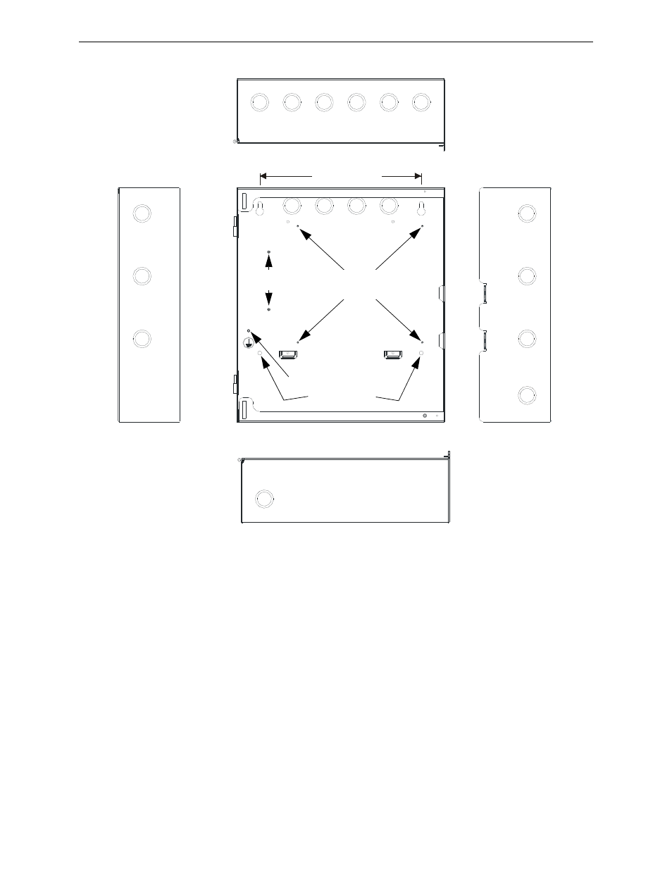
Figure 2.1 Cabinet Dimensions and Knockout Locations
41
1u
d
ac
ca
b.
wmf
Ground Stud
Top
Right side
Mounting Keyholes
10.0” (25.4cm)
Main Circuit Board
Mounting Studs
Transformer
Mounting Studs
Left side
Mounting Holes
Bottom