Aquametrix AM-TBR Turbidimeter User Manual User Manual
Page 25
20
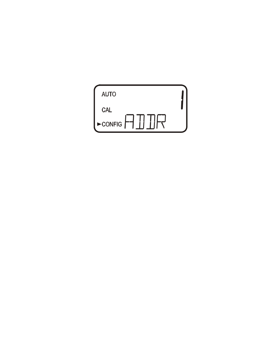
Press the ↵ button to continue on and select the desired instrument address using the or
buttons. Once the selection is satisfactory, press the ↵ button.
Select the address using or buttons. Press the ↵ button to save.
To enable the Modbus mode, select ASCII or RTU. For more information refer to a Modbus
manual
7.5. Configuring the Alarms
Two relays are provided that are designed to operate as two independent programmable alarms.
Three types of information must be input to fully program each alarm:
1. The alarm function (HI, LO, OFF or Error)
2. The alarm set point (level at which the alarm activates)
3. The delay time for the alarm: the time that the set point must be exceeded prior to alarm
activation and the time before resetting the alarm (prevents chatter in the relay)
These three items are described below:
Alarm Function: The alarms can either be turned OFF or programmed to operate in one of
three different manners:
1. HI alarm: the relay changes state when the measured turbidity level is higher than the
programmed alarm level for a prescribed amount of time.
2. LO alarm: the relay changes state when the measured turbidity level is lower than the
programmed alarm level for a prescribed amount of time.
3. Error: the relay changes state when a system error occurs. If a system error occurs a
message will appear on the lower row of the screen describing the problem.
Alarm Set Point: The level at which an alarm activates is called the alarm set point. On the
instrument, the alarm set point is designated as “S/P”. The set point is adjustable to any valid
turbidity level over the range of the instrument in steps of 0.01 NTU.
Alarm Delay Time: The alarm delay times are used to prevent ringing of the alarm when the
measured turbidity level is close to the set point. The function of the delay times is as follows:
Delay On: The turbidity level must exceed the alarm set point continuously for at least this