Aquametrix AM-TBR Turbidimeter User Manual User Manual
Page 14
9
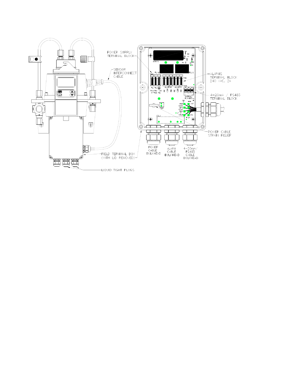
Figure 5 - Electrical Connections for the Instrument
3.3.1.
Power
The instrument is equipped with a 100-240 VAC, 47-63 Hz switching power supply; please verify
that the line voltage falls within these specifications. It is recommended that a circuit breaker be
placed prior to the power connection to allow for service. While making connections, refer to
Figure 5. The AM-TBR is not supplied with a power cord.
3.3.2. RS-485
The RS-485 half-duplex (2-wire) digital interface operates with differential levels that are not
susceptible to electrical interferences. This is why cable lengths up to 3000 ft can be
implemented. The last device on each bus may require terminating with a 120-ohm resistor to
eliminate signal reflection on the line. Do not run RS-485 cables in the same conduit as power.
To prevent damage to the instrument, ensure that power is disconnected prior to making
connections. For ease of connecting, remove the plug in terminal block. Connections are labeled
beneath this termination.
3.3.3. Relays
The Alarm 1 and Alarm 2 relays are mechanical relays rated at 240 VAC 2A. Please note that
the relays are labeled NO (Normally Open), NC (Normally Closed) and C (Common). As these
alarms are configured fail-safe, the normal condition is with power applied to the AM-TBR and in
a non-alarm condition. Operation of these alarms is covered in section 7.5 Configuring the
Alarms.