Rl5000, Nmd-100 d – Triton RL5000XP PC-BASED ATMS Installation Manual User Manual
Page 44
44
RL5000
XP
I
NsTaLLaTION
G
UIDE
R
EMOvING
/I
NsTaLLING
THE
NMD-100 D
IsPENsING
M
ECHaNIsM
The dispensing mechanism for the
RL5000
XP
unit is shipped mounted
on the slide rails inside the security
vault. Several protective foam packs
have been strategically placed behind
and along each side of the dispensing
mechanism to reduce any movement
during transit. The foam packs must
be removed before the dispensing
mechanism can be extended out. Fol-
low the procedures below for removal.
R
EMOvING
T
HE
NMD-100
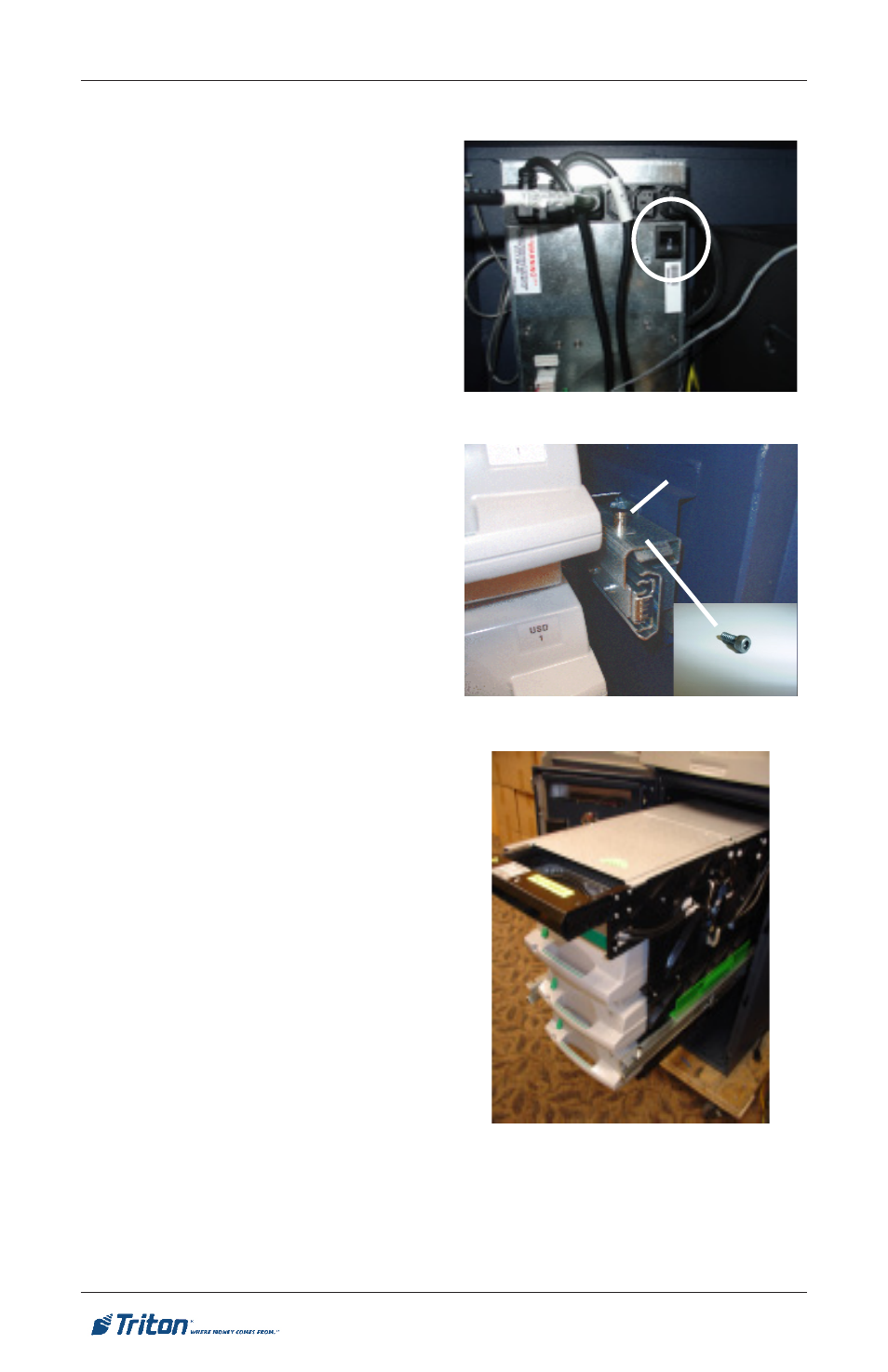
1. Unlock and open the control
panel. Verify that the power
switch located on the power
supply (rear of cabinet) is in
the OFF (0) position (Figure 1).
Close the control panel.
2. Open the security vault and re-
move all protective foam packs
from around the dispensing
mechanism.
3.* If slide rails are secured, refer
to Figure 2. Remove the trans-
port 5/32” Allen screws located
on top front of each slide rail.
4. Pull the dispensing mechanism
out of the cabinet until it reaches
its fully extended position. The
right slide rail has a locking pin
that must be disengaged to extend
the rail. (Figures 2 and 3)
6. Refer to Figures 4 and 5. Disconnect the DC power, serial communications,
and shutter cables from the dispensing mechanism. Refer to Figures 6 and
7. Remove the cables from the cable clips attached to sides of dispenser.
Figure 1. Power supply On/Off switch.
Allen screw
Locking pin
Figure 2. Transport screw location.
Figure 3. Dispenser fully extended.
5. Turn the dispenser power switch
located just to the right of the
power connector to OFF (0)
(Figure 5).