Rl5000, Ac p – Triton RL5000XP PC-BASED ATMS Installation Manual User Manual
Page 40
40
3. Install the supplied snap bushing
into the access hole that carries
the power and phone cords.
Install the supplied dome plug
into the unused access hole.
See Figure 3 for an example that
shows the snap bushing on the rear
access hole and the dome plug on the
side access hole.
4. Plug the AC power plug into the
wall outlet.
5. Plug the CAT-5 cable into the wall
mounted modular jack.
Figure 2a. Power and phone cords
routed through rear access hole.
RL5000
XP
I
NsTaLLaTION
G
UIDE
C
ONNECTING
aC P
OWER
aND
E
THERNET
C
abLE
IMPORTANT: AC power for the
terminal should come from a ded-
icated source with an isolated
ground.
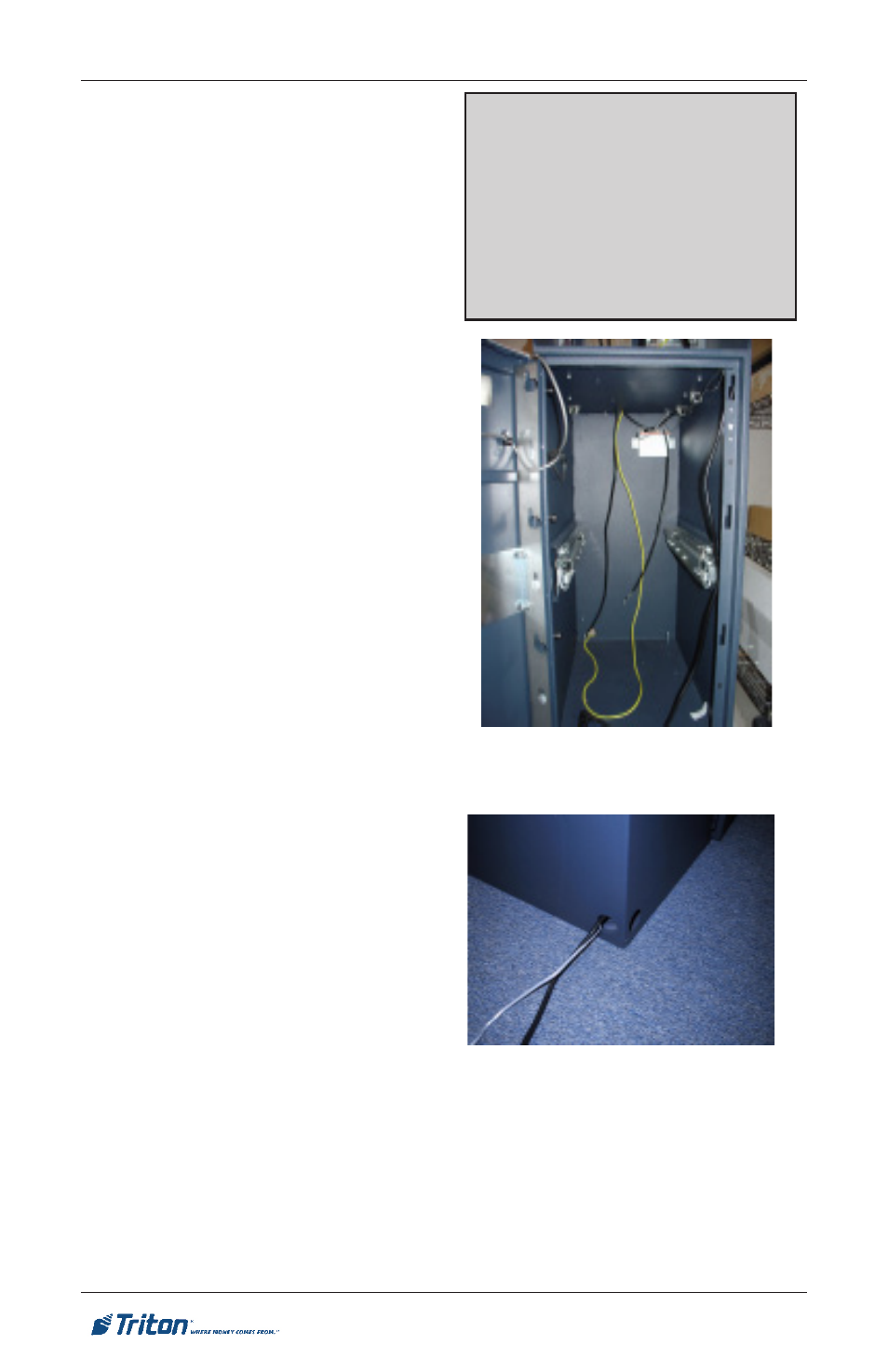
1. Ensure the power and Ethernet
(CAT-5) cables are routed through
the cable clips as shown in Figure
1.
2. Route the AC power and CAT-5
cables through either the rear or
side access hole (as applicable) in
the security cabinet as shown in
Figures 2a and 2b.
Figure 1. Ensure power and CAT-5
cables are routed through cable clips.
***WARNING***
This unit may be equipped with
more than one power cord. Dis-
connect All Power Cords prior to
Servicing! For continued fault pro-
tection, follow the correct voltage
and current ratings when replacing
any fuses.