Rl5000 – Triton RL5000XP PC-BASED ATMS Installation Manual User Manual
Page 24
24
RL5000
XP
I
NsTaLLaTION
G
UIDE
Mark the location of the cabinet
mounting holes on the concrete floor.
This is accomplished as described
below:
MARK/DRILL MOUNTING
HOLES
1. Move the ATM to the location
where it will be installed.
Open the cabinet door at least
90° degrees to improve access.
Locate the four anchor-bolt holes
(cutouts) in the bottom of the
cabinet. Use a felt-tip pen or
other marker to carefully mark
the center of each of these four
holes on the floor; these marks
will serve as guides for the anchor
bolt holes that will be drilled in
the next step. Move the ATM
aside to provide clear access to
the mounting hole marks. Center
punch each mark to help align the
drill bit.
CONCRETE STRENGTH
The floor at the installation location
should consist of commercial-grade
concrete measuring at least 2000
psi in compression strength. The
full effectiveness of the mounting
anchors depends upon meeting
this specification! Check with the
contractor/builder or owner of the
installation to verify that this re-
quirement can be satisfied.
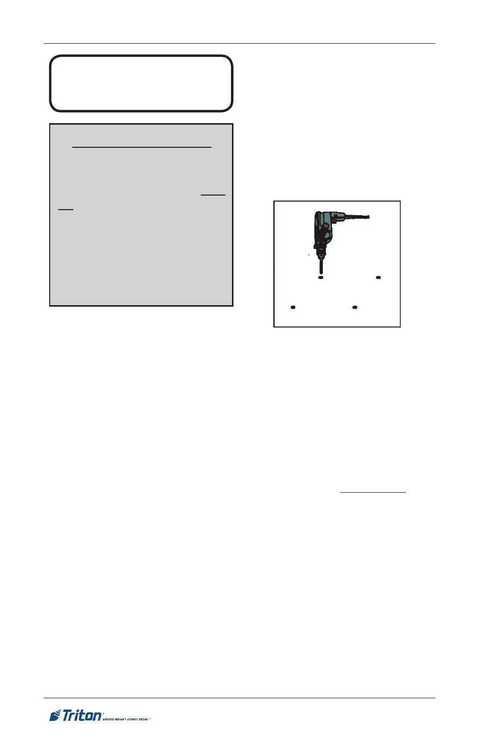
2. Use a 1/4” diameter carbide-
tipped masonry bit to drill four
pilot holes at the drilling points
marked in the previous step. Drill
the pilot holes approximately 1/2”
deep into the floor. These holes
will help guide the 1/2” masonry
bit that will be used to drill the
anchor-bolt holes in the next step.
3. Use a 1/2” diameter carbide-tipped
masonry bit to drill four holes at
least 2 3/4” deep into the floor. Be
sure to take into account the depth
of any floor covering, such as tile
or vinyl when gauging the depth
of the anchor holes. Make sure the
holes are drilled at least
2 3/4” into the concrete floor.
4. Use a portable vacuum cleaner to
remove any dust or debris that may
have fallen into the holes during
the drilling process.
Drill anchor holes