Rl5000 – Triton RL5000XP PC-BASED ATMS Installation Manual User Manual
Page 32
32
RL5000
XP
I
NsTaLLaTION
G
UIDE
MARK/DRILL
MOUNTING HOLES
Mark the location of the cabinet
mounting holes on the concrete floor.
This is accomplished as described
below:
1. Move the ATM to the location
where it will be installed.
Open the cabinet door at least
90° degrees to improve access.
Locate the four anchor-bolt holes
(cutouts) in the bottom of the
cabinet. Use a felt-tip pen or
other marker to carefully mark
the center of each of these four
holes on the floor; these marks
will serve as guides for the anchor
bolt holes that will be drilled in
the next step.
Move the ATM aside, to provide
clear access to the mounting hole
marks.
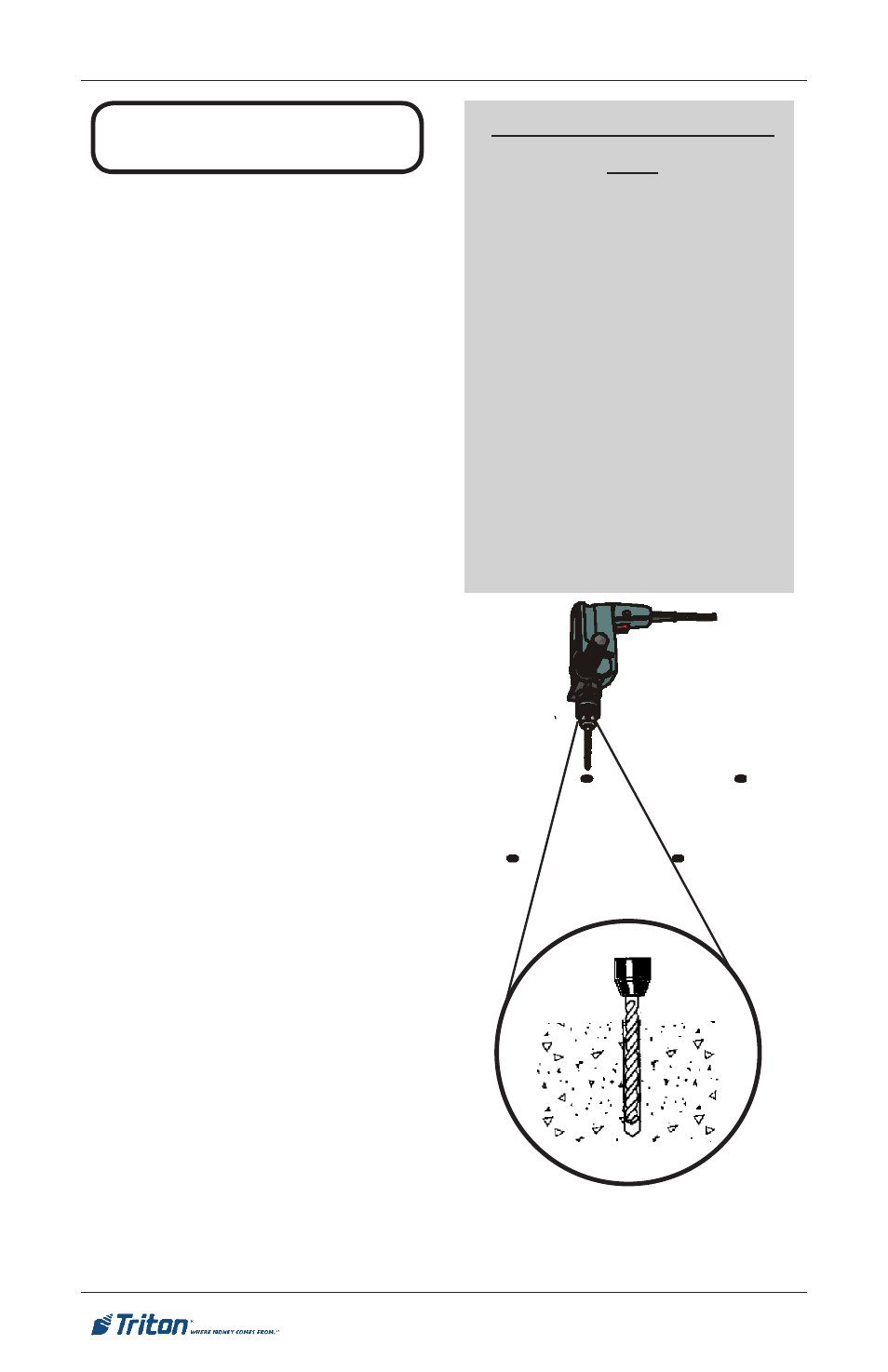
Fig. 1. Drilling mounting holes.
2. Use a 6 mm (1/4”) diameter
carbide-tipped masonry bit
to drill four pilot holes at the
drilling points marked in the
previous step. Drill the pilot holes
approximately 12 mm (1/2”)
deep into the floor. These holes
will help guide the 1/2” masonry
bit that will be used to drill the
anchor-bolt holes in the next step.
CHEMICAL ANCHOR SYS-
TEM
The chemical anchor installation
system used in this procedure
bonds threaded anchor-rod inserts
to the base material (for ATM
applications this is typically a
concrete foundation). Unlike tra-
ditional expansion-bolt anchoring
systems, chemical anchoring is
accomplished without exerting
expansion forces against the base
material. As a result, the chemical
anchoring system proves ideal for
anchoring in a wider selection of
materials from brick to granite.