Rl5000 – Triton RL5000XP PC-BASED ATMS Installation Manual User Manual
Page 34
34
RL5000
XP
I
NsTaLLaTION
G
UIDE
1. Move the ATM into position for
mounting by aligning the base
over the four holes drilled in the
previous procedure.
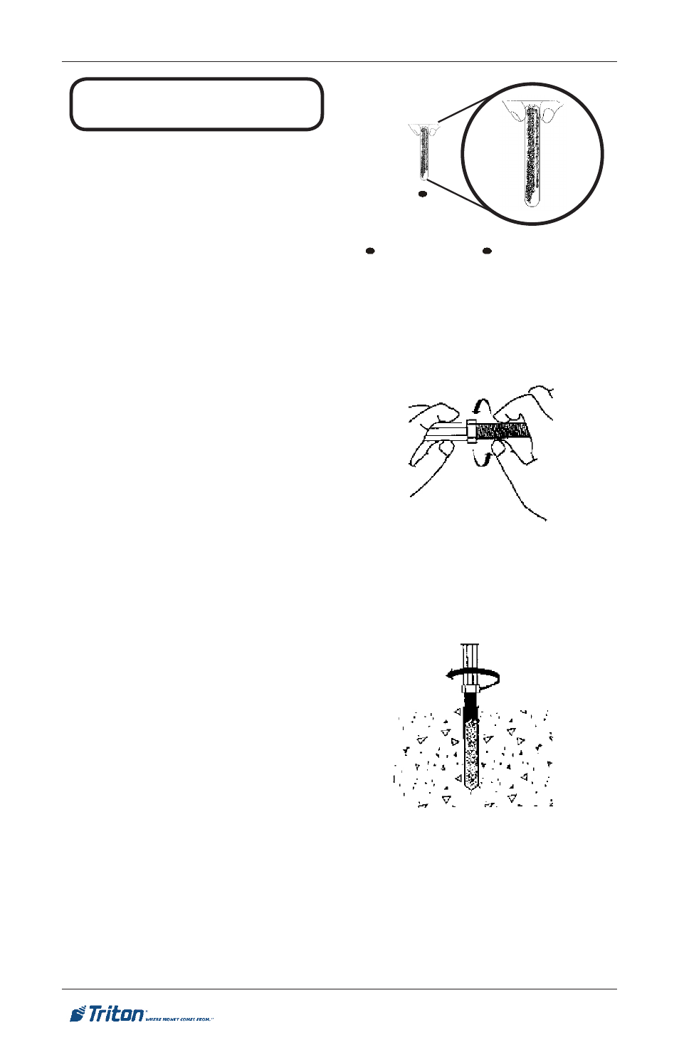
2. Begin by inserting a chemical
stud capsule into one of the
mounting holes. Either end of the
capsule may be inserted first.
3. Place a washer and a nut (in
that order) onto a chisel point
rod. Thread the nut onto the rod
leaving 3 to 4 threads exposed.
4. Thread the rod coupler onto
the threaded rod until it is tight
against the nut. The threaded rod
used should be free of dirt, grease,
oil or other foreign material.
5. Select the drive unit, insert it into
a rotary hammer drill and engage
the coupling to be used.
6. Insert the chisel point of the
rod into the hole to break the
glass capsule. Spin it into
the capsule at a speed of 250
to 500 RPM until it is fully
embedded. IMPORTANT! Turn
the rotary hammer drill OFF
IMMEDIATELY when the rod
is fully embedded!
7. Pull the driver out of the coupling
while holding the rod. Hold the
hex nut with a wrench to unthread
the coupler.
Fig. 4. Insert chemical stud
capsule in mounting hole.
Fig. 5. Prepare chisel point anchor
rod. Add washer and nut.
Fig. 6. Drive anchor rod into
capsule using hammer drill.
INSTALL CHEMICAL
ANCHORS