LumaSense Technologies 3434i SF6 Leak Detector User Manual
Page 10
Chapter 1
______________________________________________________________________
_____________________________________________________________________________
BE6028-14
3434i SF6 Leak Detector
LumaSense Technologies A/S
Page 10 of 191
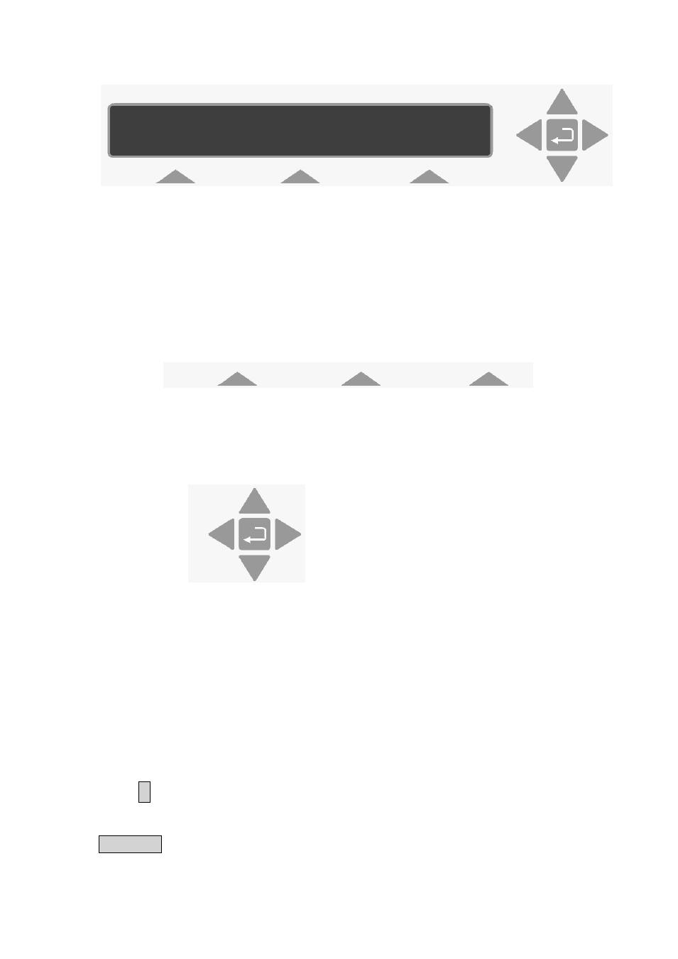
The display above is used continuously through-out this manual. It
assists you displaying the text on screen and by indicating which of
the push-buttons can and should be pressed.
In general, the push-buttons shown above are used to navigate
through the various modes possible within the 3434i but are
described in more detail below:
These push-buttons are illustrated as S1, S2 and S3. On the 3434i
they correspond to the key and their position on the instrument.
These select push-buttons enable you to select one of the options
displayed.
This group of 5 push-buttons are referred to in this manual
collectively as the direction keys. The symbols below are used to
simplify the instruction in this manual.
▲ & ▼ enable you to increase & decrease numbers, respectively, or
to go to the Previous & Next Displays, respectively.
◄ & ► enable you to move across number fields or go to the
Previous & Next gases, respectively.
¿
, depending on the situations, acts as an “Enter” or “Go To Head”
key.
Memory Function push-buttons are always represented with the name
of the push-button enclosed in a box which is shaded-in.
SELECT SET-UP BRANCH
MEASUREMENT
FORMAT
CONFIGURATION
S1 S2 S3