Brocade Flow Vision Administrators Guide (Supporting Fabric OS v7.3.0) User Manual
Page 41
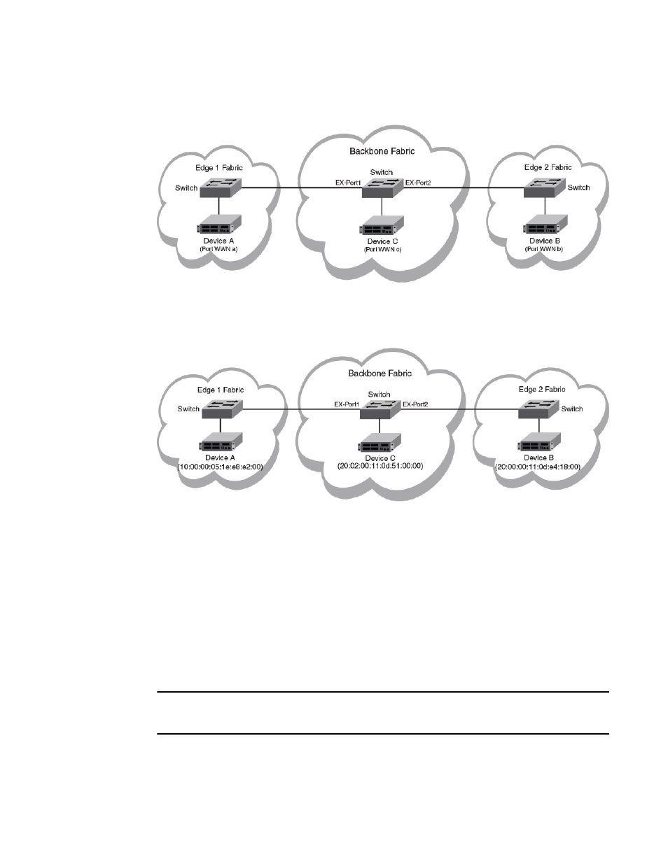
FIGURE 3 A Fibre Channel router fabric
The following figure provides the port WWN values for the physical devices and port WWNs.
FIGURE 4 A Fibre Channel router fabric annotated with port WWN values
Monitoring an edge-to-edge flow through an ingress port identified by a WWN
In a network set up as shown in
on page 41, for a flow passing from Device A to Device B that
is ingressing through EX_Port1, the source device (srcdev) is port “WWN a”, the destination device
(dstdev) is port “WWN b”, and the ingress port (ingrport) is EX_Port1. (Traffic is running from right to
left, and the flow definitions are based on the Edge 1 Fabric’s perspective.)
The following example creates a flow that filters frames passing from one edge fabric to another edge
fabric using a specific ingress port on the backbone. The first command shows the available ports and
the available Fibre Channel routers. The second command creates a Flow Monitor flow named
“e2e_src_dcx_wwn” between device 10:00:00:05:1e:e8:e2:00 and device 20:00:00:11:0d:e4:18:00
ingressing through port 219, and the last command displays the results of the flow.
NOTE
The slash character (\) in the example indicates a break inserted because the output is too long to
display here as a single line.
DCX_Backbone128:admin> switchshow |grep Port
Index Slot Port Address Media Speed State Proto
37 3 5 012500 id N16 Online FC EX-Port 10:00:00:05:33:ef:f1:1c \
47 3 15 012f00 id N8 Online FC F-Port 20:02:00:11:0d:51:00:00 \
Monitoring an edge-to-edge flow through an ingress port identified by a WWN
Flow Vision Administrators Guide
41
53-1003168-01