Yokogawa PR300 Power and Energy Meter User Manual
Page 62
Appendix
A-5
IM 77C01E01-01E
1
2
3
4
5
A
Appendix 1 Specifications of PR300
Example of connection diagram
(SG)
(SG)
(SG)
(B
؉)
(A
؊)
(B
؉)
(A
؊)
(FG)
Terminator
RS-485
RS-485
RS-485
Maximum distance: about 1.2 km (31 units maximum)
PC
RS-232C/RS-485
converter
RS-232C
straight
cable
120
⍀ external
PR300
PR300
PR300
For RS-485 communication, the PR300 employs the two-wire system.
SG: Connection to Terminal SG is made to adjust the signal level of the RS-485 communication line.
FG: For noise protection, a shield line must be connected to all wires in the RS-485 communication line and grounded
at one location.
Use UL Listed RS-232C/RS-485 converter if the converter has AC/DC power supply input; this is optional for
converters supplied by a Limited Power Source with input voltages less than 30 V AC or 60 V DC and which are
separated from mains by double or reinforced insulation.
120
⍀ (built-in)
(A
؊)
(TERM)
(SG)
(B
؉)
(A
؊)
(B
؉)
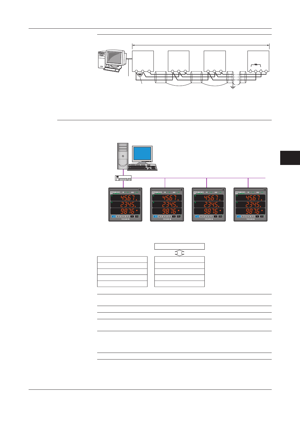
Ethernet communication
Via Ethernet communication, various measured values are read, and values are written to
various parameters using the command/response method.
PC
IP address [192.168.1.1]
Ethernet
LAN connection
HUB
Station number 01
IP address [192.168.1.2]
Station number 01
IP address [192.168.1.3]
Station number 01
IP address [192.168.1.4]
Station number 01
IP address [192.168.1.5]
(Example)
Connectable to an IEEE802.3-compliant network (10BASE-T/100BASE-TX).
Application layer
Transport layer
Network layer
Data link layer
Physical layer
MODBUS/TCP
TCP, UDP
IP, ICMP, ARP
Ethernet
10BASE-T/100BASE-TX
Higher-level device (PC etc.)
Communication specifications
Protocol
Modbus/TCP
Access control
CSMA/CD
Baud rate
10Mbps/100Mbps
Maximum segment length
100m (between HUB and module)
Maximum connection configuration
Cascade
4 segments maximum (10BASE-T)
2 segments maximum (100BASE-TX)
(number of HUBs that can be cascade connected)
IP address
The IP address can be set using the operation keys on the front side of the PR300.