Checking the package, Checking the model and suffix codes, Force majeure – Yokogawa PR300 Power and Energy Meter User Manual
Page 4
iii
IM 77C01E01-01E
■
Force Majeure
• Yokogawa does not make any warranties regarding the product except those mentioned in the
WARRANTY that is provided separately.
• Yokogawa assumes no liability to any party for any loss or damage, direct or indirect, caused by the
use or any unpredictable defect of the product.
• Be sure to use the spare parts approved by Yokogawa when replacing parts or consumables.
• Modification of the product is strictly prohibited.
• Reverse engineering such as the disassembly or decompilation of the product is strictly prohibited.
• No portion of the product supplied by Yokogawa may be transferred, exchanged, leased, or sublet for
use by any third party without the prior permission of Yokogawa.
Checking the Package
Verify the package as explained below before starting to use the product. Should the delivered product
be wrong or the package be missing any item, contact the vendor from which you purchased the product.
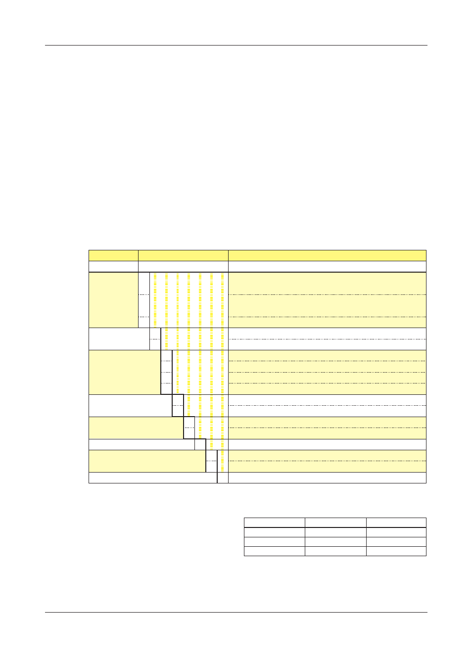
Checking the Model and Suffix Codes
The PR300 bears a nameplate. Confirm that “MODEL” and “SUFFIX” (suffix codes) shown on the
nameplate agree with those of the product ordered.
Model
PR300
Phase and
wire system
Input voltage/
input current
Additional input and
output function
Communication function
Optional measuring function
Power supply
Phase indication format
Suffix Codes
-
ٗ ٗ ٗ ٗ ٗ -6 ٗ -0
-3
-4
-5
1
2
0
1
2
3
0
3
0
3
-6
A
R
-0
Description
Power and Energy Meter
Universal three-phase three-wire system (single-phase two-wire,
single-phase three-wire, and three-phase three-wire systems)
Universal three-phase four-wire system (single-phase two-wire, single-
phase three-wire, three-phase three-wire, and three-phase four-wire systems)
Three-phase four-wire system (2.5 element)
*1
Universal voltage input
*2
(150 V, 300 V, 600 V) / 1 A
Universal voltage input
*2
(150 V, 300 V, 600 V) / 5 A
1 digital input
1 digital input, 1 analog output
1 digital input, 1 pulse output
1 digital input, 1 analog output, 1 pulse output
RS-485 communication
RS-485 communication, Ethernet communication
*3
None
Demand measurement (1 demand alarm output)
100-240 V AC
±10% (50/60 Hz) or 130-300 V DC ±15%
A, B, and C indications
R, S, and T indications
Always 0
*1 Can be used only when the voltage is in a state of equilibrium.
In cases where “Three-phase four-wire system (2.5 element)” is specified,
the input current specification of 1 A AC is not applicable.
*2 Set the voltage range (150 V, 300 V or 600 V) according to the rated input
voltage to be measured.
*3 For Ethernet communication, the RS-485 communication interface is
exclusively for the Ethernet-serial gateway function.
Rated input voltage
120 V
240 V
480 V
Voltage range
150 V
300 V
600 V
Allowable input voltage
150 V
300 V
600 V
Serial Number (NO.)
Also inform this number shown in “NO.” on the nameplate when contacting the vendor from which you
purchased the PR300.