Range of phase and wire system options, Range of phase and wire system options -3 – Yokogawa PR300 Power and Energy Meter User Manual
Page 19
Preparations before Starting Measurement (Set up the PR300 First)
2-3
IM 77C01E01-01E
1
2
3
4
5
A
I
2.2
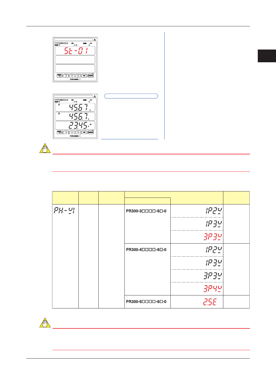
Setting the Phase and Wire System
Measured Value screen
Startup screen
The PR300 shows the Startup
screen for about 5 seconds, then the
Measured Value screen appears.
Setting completed.
NOTE
If you change the phase and wire system, all parameters other than those related to RS-485 and
Ethernet communications are initialized (to factory-set values). Change the phase and wire system
before setting parameters such as the VT and CT ratios.
Range of Phase and Wire System Options
Parameter
Symbol
Model and Suffix Codes
Parameter
Name
Setting Type
Setting Range (Details)
Initial Value
(Factory-set
Value)
Phase and
wire system
Selection
Single-phase
two-wire system
Single-phase
three-wire system
Three-phase
three-wire system
Single-phase
two-wire system
Single-phase
three-wire system
Three-phase
three-wire system
Three-phase
four-wire system
Three-phase
four-wire system
(2.5 element)
Three-phase
three-wire
system
Three-phase
four-wire
system
Three-phase
four-wire system
(2.5 element)
NOTE
●
If single-phase three-wire system is selected, the voltage range is fixed at 300 V (between P0 and
P1, P0 and P2). The voltage range cannot be selected.
●
Three-phase four-wire system (2.5 element) can be used only when the voltage is in a state of
equilibrium. In addition, the phase and wire system cannot be changed.