Communication specifications, Demand alarm output specifications – Yokogawa PR300 Power and Energy Meter User Manual
Page 61
A-4
IM 77C01E01-01E
Appendix 1 Specifications of PR300
Demand Alarm Output Specifications (optional measuring function)
When the demand measurement value exceeds the set demand alarm point, an alarm is triggered.
Output signal
Open collector
Contact capacity
30 V DC, 200 mA
Set alarm range
1 to 1000 kW (during demand power measurement); 1 to 1000 A (during demand current measurement)
Alarm release function
Automatic release:When the measured value falls below the demand alarm point during alarm
output, the alarm is canceled.
Manual release:
Used to keep the alarm turned on or to cancel it by digital input or the
operation key, or via communication.
* The demand alarm mask time can be set for the PR300.
The demand alarm mask time is the time between the beginning of the demand period and the
set time, during which an alarm is not recognized.
Allowable range of set time: 1 minute to demand period
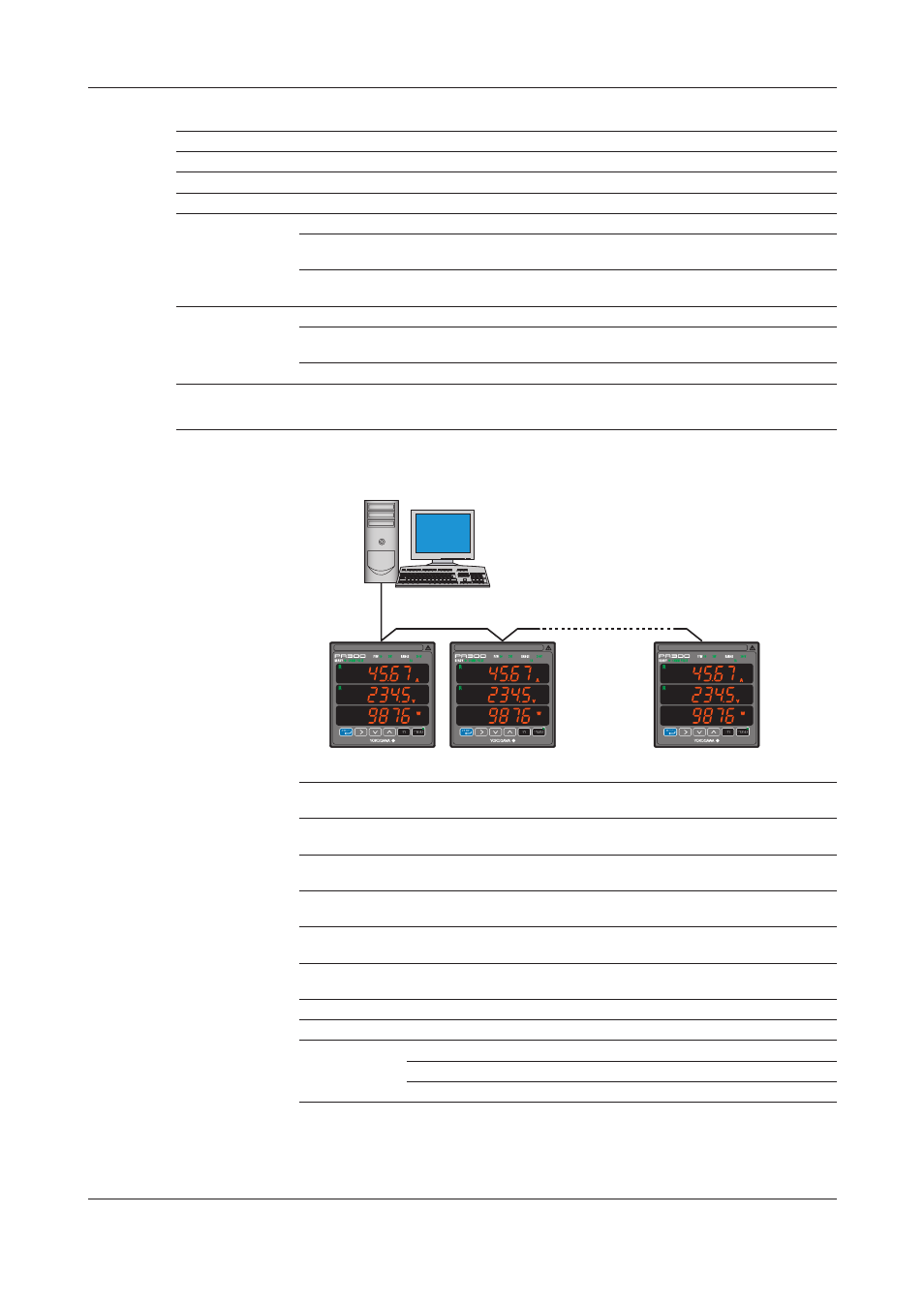
Communication Specifications
RS-485 communication
Via RS-485 communication, various measured values are read, and values are written to
various parameters using the command/response method.
Maximum communication distance: 1.2 km
Maximum number of connectable slave stations: 31
PC
Station number 01
Station number 02
Station number 31
(Example)
Protocol
PC link (without checksum), PC link (with checksum), Modbus/ASCII, and
Modbus/RTU
Transmission distance
Approximately 1.2 km maximum (with 24AWG twisted-pair cable(s))
Connection method
Multi-drop connection (a maximum of 32 units including a higher-level device)
Station number
01 to 99 (maximum number of units to be connected: 31 [number of units
that can be connected to a PC etc.]) (recommended value: 01 to 31)
Transmission method
Half-duplex communication
Synchronization
Start-stop synchronization
Baud rate
19200/9600/2400 bps
Xon/Xoff control
None
Data format
Data length
8 bits, 7 bits
Parity
None, even, odd
Stop bit
1 bit, 2 bits