Parameter setting types and ranges (continued) – Yokogawa PR300 Power and Energy Meter User Manual
Page 39
3-18
IM 77C01E01-01E
3.9
Setting the Measured Value Display Pattern
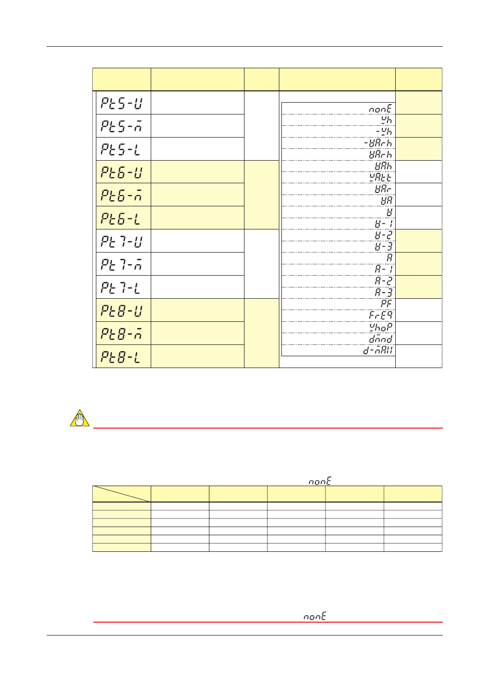
Parameter Setting Types and Ranges (Continued)
Voltage-2
Voltage-3
Current
(phase switch
inidication)
Voltage
(phase switch
inidication)
Frequency
Current
(phase switch
inidication)
Active power
Power factor
Active power
Maximum
demand value
Demand value
Display pattern-5 upper display
Display pattern-5 middle display
Display pattern-5 lower display
Display pattern-6 upper display
Display pattern-6 middle display
Display pattern-6 lower display
Display pattern-7 upper display
Display pattern-7 middle display
Display pattern-7 lower display
Display pattern-8 upper display
Display pattern-8 middle display
Display pattern-8 lower display
Selection
Selection
Selection
Selection
A measurement item can be selected from the
following:
None
Active energy
Regenerative energy
LEAD reactive energy
LAG reactive energy
Apparent energy
Active power
Reactive power
Apparent power
Voltage (phase switch inidication)
Voltage-1
Voltage-2
Voltage-3
Current (phase switch inidication)
Current-1
Current-2
Current-3
Power factor
Frequency
Optional active energy
Demand value
Maximum demand value
Voltage-1
Parameter Symbol
Parameter Name
Setting
Type
Setting Range (Details)
Initial Value
(Factory-set
Value)
Number of Display Patterns and Individual Display Patterns
Allocate desired measurement items to the upper, middle and lower displays of the PR300, respectively, to define
the display view as a single display pattern. It is possible to define a maximum of 8 patterns. For the number of
display patterns, specify how many of these defined display patterns the PR300 should show.
NOTE
●
As shown in the table below, some measurement items cannot be measured depending on the type
of phase and wire system. Measurement items that cannot be measured cannot be selected as
options for a display pattern.
●
In the case of a three-phase four-wire system, the initial values of Display patterns-1 to 8 can all be
shown on the PR300. For phase and wire systems other than a three-phase four-wire system,
measurement items that cannot be measured are shown as “
”.
Current
Current-1
Current-2
Current-3
Voltage-2
Voltage-3
Single-phase
two-wire system
–
✔
–
–
–
–
Single-phase
three-wire system
✔
✔
✔
–
✔
–
Three-phase
three-wire system
✔
✔
–
✔
–
✔
Three-phase
four-wire system
✔
✔
✔
✔
✔
✔
Three-phase four-wire
system (2.5 element)
✔
✔
–
✔
–
✔
✔
: Measurable. –: Not measurable.
*1
*1
*1
(phase switch
inidication)
Measurement item
Phase and wire
system
*1 For a three-phase four-wire system (2.5 element), it is possible to set the following measurement items
only when the current is in a state of equilibrium:
Current (phase switch indication), Current-1, Current-3, Reactive power, Apparent power, Power factor,
LEAD reactive energy, LAG reactive energy, and Apparent energy.
●
The demand value and maximum demand value can only be selected for a PR300 with the demand
measuring function. For a PR300 without the demand measuring function, the initial values of
demand value and maximum demand value are shown as “
”.