3 wiring, Crimping terminal recommendations, Wiring -5 – Yokogawa PR300 Power and Energy Meter User Manual
Page 12: Crimping terminal recommendations -5, Warning
1-5
IM 77C01E01-01E
1
1
2
3
4
5
A
I
Installation and Wiring
1.3
Wiring
WARNING
●
As there is a danger of electric shock, turn off the power supply and check that the cables to be
connected are not conducting electricity before carrying out the wiring procedure.
●
For safety, be sure to install a circuit breaker switch that conforms to IEC60947 near the PR300 so
as to be operated easily, and clearly indicate that the device is used to de-energize the PR300.
●
The wiring procedure for the PR300 should be carried out by a qualified person (an electrician etc.)
with knowledge of electrical matters and who has actual experience.
●
Install a current transformer (CT) inside a panel when using a conduit for wiring.
●
Use a UL Listed Panel only for the panel on which the PR300 is installed.
●
If the voltage is below 600 V AC, it is possible to connect the PR300 directly without using a voltage
transformer (VT) and if the current is below 5 A AC, it is possible to do so without using a current
transformer (CT). However, in order to use the PR300 safely, the use of VT and CT is recom-
mended. Use a UL Listed VT and CT for the PR300.
●
Perform wiring for the voltage and current input in the same circuit.
●
Check the following before turning on the power. Using the PR300 beyond the stated specifications
may cause it to heat up and burn out.
• Check that the power supply voltage, input voltage, and input current values to be applied to the
PR300 agree with its specifications.
• Check that the external wiring is connected to the terminals in accordance with the specifica-
tions.
●
Do not touch the screws in locations (a) to (f) shown in the wiring diagrams. They are an essential
part of the structure of the PR300. Loosening or tightening them may result in a malfunction or
failure of the PR300.
●
Be sure to attach the terminal cover to prevent electric shock (refer to Section 1.4) .
NOTE
●
When attaching the terminal cover
Since the terminal cover of PR300 has the structure of preventing electric shock, the terminal cover
cannot be attached after completing all wiring. Refer to Section 1.4, “Attaching the Dust Cover and
Terminal Cover” before wiring.
(1) Attach the terminal cover after completing the wiring to the terminals 2, 4, 6, 8, 23, 24, and 25.
(2) Execute the wiring to the terminals other than those mentioned above after attaching the
terminal cover.
If the dust cover is required, attach it before attaching the terminal cover.
●
Do not ground the input circuit when connecting voltage and current directly without using VT and CT.
Carry out the wiring referring to the diagrams on pages 1-6, 1-7, and 1-8. The wiring for voltage input,
current input, and power supply is M4 screw terminal connection. For other wiring it is M3 screw terminal
connection. The connector for connecting to the Ethernet is RJ45.
Use strand wires for the wiring. Wiring cables with a nominal cross-sectional area of 1.25 mm
2
or thicker
are recommended for voltage/current input and power supply; cables with a nominal cross-sectional area
of 0.5 mm
2
or thicker are recommended for other signals.
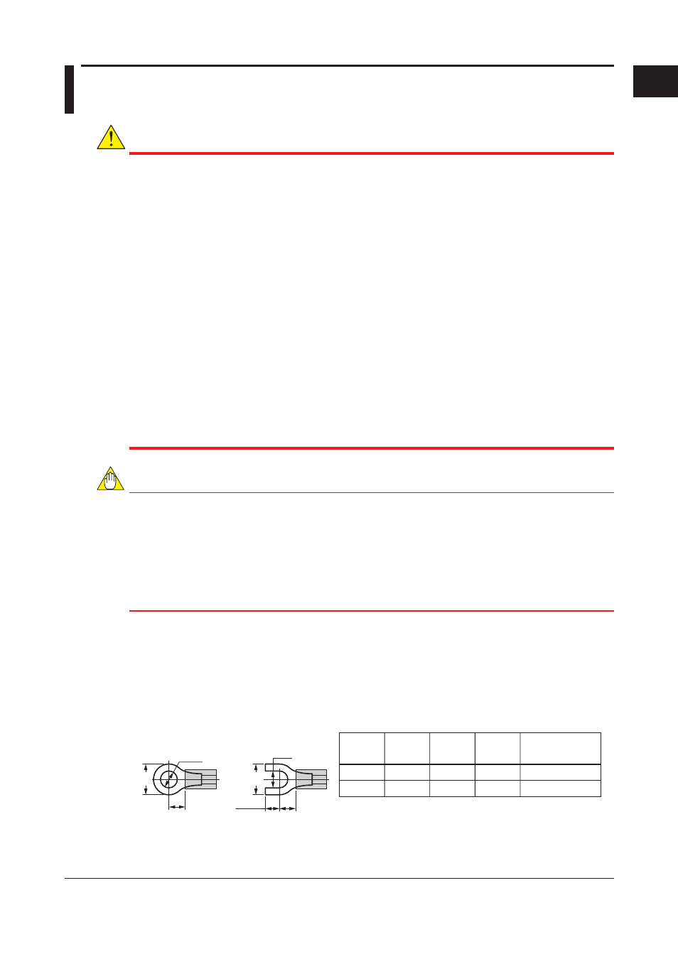
Crimping Terminal Recommendations
(A)
(F)
(F)
4.7 max.
(ød
)
M4
M3
4.4 max.
3.3 max.
7.0 max.
5.8 max.
7.8 max.
6.7 max.
1.2 N
•m
0.6 N
•m
ød (mm)
Applicable
terminals
A (mm)
F (mm)
Recommended
tightening torque
Ring tongue
terminal
Spade tongue
terminal
(A)
(ød
)
Applicable wire size: 1.04 to 2.63 mm
2
for M4, 0.25 to 1.65 mm
2
for M3