10 software write protection, 11 alarm, Software write protection -23 – Yokogawa EJX930A User Manual
Page 34: Alarm -23
<3. Parameter Setting>
3-23
IM 01C25R02-01E
3.3.9 CPU Failure Burnout Direction and
Hardware Write Protect
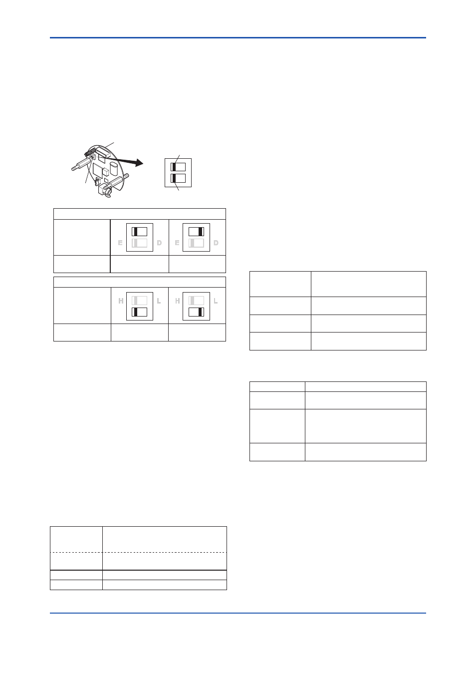
There are two slide switches on the CPU assembly
board. One sets the burnout direction at CPU
failure, and the other sets a write protection function
which disables parameter changes through
the use of a handheld terminal or some other
communication method.
HIGH
LOW
CPU assembly
Slide switch
Burnout direction switch
Write protection switch
Write Protection
Switch Position
Burnout Direction
Switch Position
BO H
L
WR E
D
H
L
E
D
H
L
E
D
H
L
H
L
Hardware write protection switch (WR)
Burnout direction switch (BO)
Burnout Direction
Write Protection
YES
(Write disabled)
NO
(Write enabled)
F0305.ai
The parameter of
AO alm typ parameter displays
the status of 4-20 mA DC output if a CPU failure
occurs. In case of a failure, communication is
disabled.
Standard specifications or with option code /C3
The burnout direction switch is set to “HIGH”. If a
failure occurs, the transmitter outputs a 110% or
higher signal.
With option code /C1 or /C2
The burnout direction switch is set to “LOW”.
If a failure occurs, a –2.5% or lower output is
generated.
To confirm the burnout direction at the CPU failure,
follow the procedure below.
• Procedure to call up the display
DD (HART 5/7)
DTM (HART 7)
[Root Menu] → Detailed setup →
Output condition → Analog output →
AO alm typ
DTM (HART 5) Configuration → Analog output → AO
alm typ
High
Burnout direction is set to High
Low
Burnout direction is set to Low
3.3.10 Software Write Protection
EJX multivariable transmitter configured data is
saved by using a write protection function. The
write protection status is set to “Yes” when 8
alphanumeric characters are entered in the
New
password field and transferred to the transmitter.
When write protection is set to ”Yes,” the transmitter
does not accept parameter changes. When the
same eight alphanumeric string entered in the
New
password field is also entered in the Enable wrt
10min field and transferred to the transmitter, it
will be possible to change transmitter parameters
during a 10 minute period.
To change the transmitter from the write protection
”Yes” status back to write protection ”No” status,
use
Enable wrt 10min to first release the write
protection function and then enter eight spaces in
the
New password field.
• Procedure to call up the display using DD
(HART 5/HART 7) and DTM (HART 7)
DD (HART 5/7)
DTM (HART 7)
[Root Menu] → Detailed setup →
Device information → Field device
info → Wrt protect menu →
→ Write Protect
Display current protect mode
(Yes: protected, No: not protected)
→ Enable wrt 10
min
Release the protect function for 10
min.
→ New password Set the new password or change
the password
• Procedure to call up the display using DTM
(HART 5)
DTM (HART 5) Write Protect →
→ Write Protect Display current protect mode
(Yes: protected, No: not protected)
→ Enter new
password
Enter the password here to enable
the protect function.
Enter eight spaces to disable the
protect function.
→ Enable write Enter the password here to release
the protect function for 10 min.
3.3.11 Alarm
The function is used to display the alarm codes
when the input differential pressure exceeds the
specified value within the calibration range. The
same is available for the input static pressure,
external temperature, and flow rate. Refer to table
4.5 Alarm Message Summary for the specific alarm
code to be generated.