Yokogawa EJX930A User Manual
Page 32
<3. Parameter Setting>
3-21
IM 01C25R02-01E
(1) Auto Sensor Trim
Applying reference pressure of 0% and 100% of the
measurement range to the transmitter, adjust the
lower and upper points automatically.
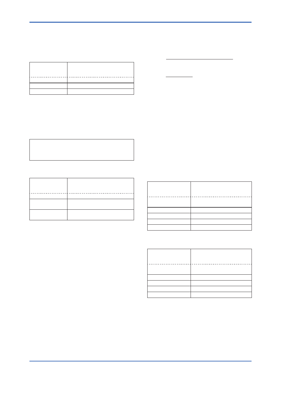
• Procedure to call up the display
DD (HART 5/7)
DTM (HART 7)
[Root Menu] → Diag/Service →
Calibration → Pres sensor trim →
Pres trim →
DTM (HART 5)
Calibration → Pressure trim →
→ Auto, Lower Pt
Auto trim for 0% point
→ Auto, Upper Pt
Auto trim for 100% point
(2) Manual Sensor Trim
Using the example below, follow the steps to
perform the full sensor trim by manually. The Pres
LTD (Manual, Lower Pt) and Pres UTD (Manual,
Upper Pt) represent the previously adjusted values.
Example: For the range of 1000 to 3000 mmH
2
O
Pres LTD (Manual, Lower Pt) = −4.0 mmH
2
O
Pres UTD (Manual, Upper Pt) = −3.0 mmH
2
O
<1> Call up the
Manual, Lower Pt.
• Procedure to call up the display
DD (HART 5/7)
DTM (HART 7)
[Root Menu] → Diag/Service →
Calibration → Pres sensor trim →
Pres trim →
DTM (HART 5)
Calibration → Pressure trim →
→ Manual, Lower
Pt
Manual trim for 0% point
→ Manual, Upper
Pt
Manual trim for 100% point
<2> Suppose that a standard pressure of 1000
mmH
2
O is applied and the value of the “Pres
for trim” is 994.0. Correct for this output error
of 6 mmH
2
O by adding 6 mmH
2
O to
Pres LTD
(Manual, Lower Pt).
−4.0+6.0=+2.0
<3> Enter the correction value of “2” to the
Pres
LTD (Manual, Lower Pt).
<4> Call up the
Pres UTD (Manual, Upper Pt).
<5> Suppose that a standard pressure of 3000
mmH
2
O is applied and the value of the Pres for
trim is 3015.0. Firstly, obtain the slope error for
the span as follows;
Slope Error =
Applied Pressure Value−Value of Pres for Trim
× (URV−LRV)
Applied Pressure Value
=
3000−3015
× (3000−1000) = −10
3000
Then correct for this slope error of −10 by
adding −10 to
Pres UTD (Manual, Upper Pt).
−3.0+(−10.0)=−13.0
<6> Enter the correction value of “−13” to the
Pres
UTD (Manual, Upper Pt).
(3) Sensor Trim for Static Pressure or External
Temperature
For the EJX multivariable transmitter, full sensor
trim of the static pressure or external temperature is
performed in the same way as with the differential
pressure.
• Procedure to call up the display for static
pressure
DD (HART 5/7)
DTM (HART 7)
[Root Menu] → Diag/Service
→ Calibration → SP sensor
trim → SP trim →
DTM (HART 5)
Calibration → Static Pressure
trim →
→ Auto, Lower Pt
Auto trim for 0% point
→ Auto, Upper Pt
Auto trim for 100% point
→ Manual, Lower Pt
Manual trim for 0% point
→ Manual, Upper Pt
Manual trim for 100% point
• Procedure to call up the display for external
temperature
DD (HART 5/7)
DTM (HART 7)
[Root Menu] → Diag/Service
→ Calibration → ET Sensor
trim → ET trim →
DTM (HART 5)
Calibration → External Temp
trim →
→ Auto, Lower Pt
Auto trim for 0% point
→ Auto, Upper Pt
Auto trim for 100% point
→ Manual, Lower Pt
Manual trim for 0% point
→ Manual, Upper Pt
Manual trim for 100% point
(4) Reset Trim Adjistment to Factory Setting
The
Clear P trim, Clear SP trim and Clear ET trim
commands can reset the trim adjustment to the
initial calibrated values that were set. The amount of
the adjustment performed with the external zero-
adjustment screw is returned to the initial setting as
well.