6 differential pressure signal low cut mode setup, 7 impulse line connection orientation setup, Impulse line connection orientation setup -16 – Yokogawa EJX930A User Manual
Page 27
<3. Parameter Setting>
3-16
IM 01C25R02-01E
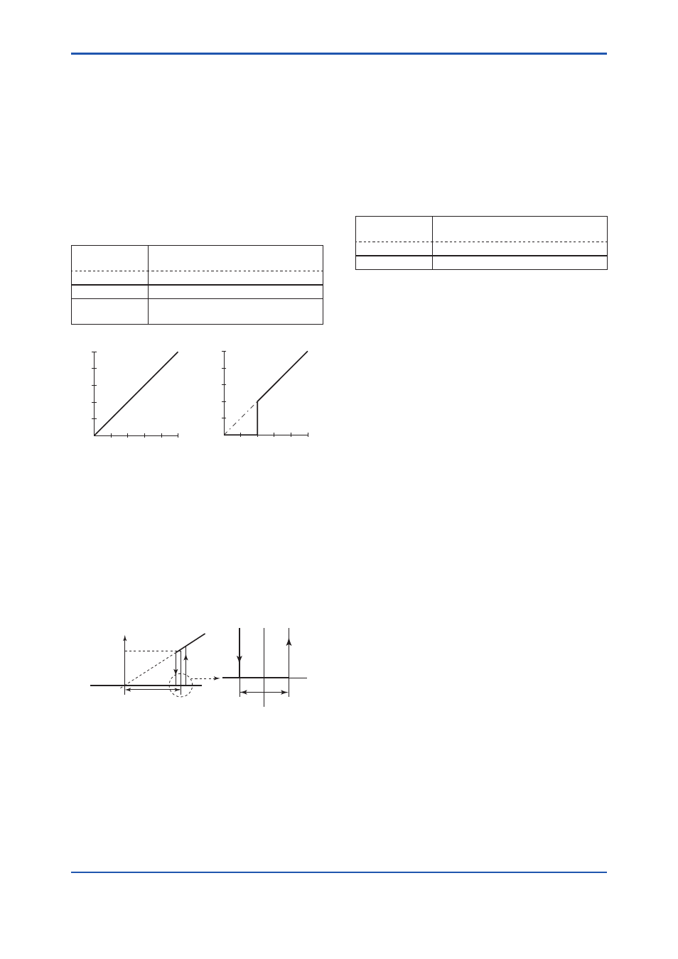
3.2.6 Differential Pressure Signal Low Cut
Mode Setup
Low cut mode can be used to stabilize the
differential pressure output signal near the zero
point. The Low cut is applied to the differential
pressure used to flow calculation. The low cut point
can be set from 0 to 20% of output. (Hysteresis for
the cut point: ±10% of the cut point )
Follow the procedure below to change the Low cut
mode and Low cut point.
• Procedure to call up the display
DD (HART 5/7)
DTM (HART 7)
[Root Menu] → Basic setup →
Others →
DTM (HART 5) Configuration → Analog Output →
→ Low cut
Set from 0 to 20% of output
→ Low cut
mode
Select “On” or “Off”
(%)
50
(%)
50
0
50
(%)
50
(%)
DP
Output
DP
Output
For low cut in Off mode
Input
20
20
0
For low cut in On mode
Input
F0302.ai
Figure 3.1
Low Cut Mode
The low cut point has hysteresis so that the output
around the point is behaved as below figure.
Low cut mode: On
Low cut: 20.00%
F0303.ai
Setting range: 0 to 20%
2%
2%
4mA
DP Output
Low cut point
Input
Hysteresis
fixed at 10%
of the cut point
7.2mA(20%)
3.2.7 Impulse Line Connection Orientation
Setup
This function reverses the impulse line orientation.
This function is used when the high pressure side
impulse line and the low pressure side impulse line
are connected reverse by mistake.
Follow the procedure below to assign the high
pressure impulse line to the L side of the transmitter.
• Procedure to call up the display
DD (HART 5/7)
DTM (HART 7)
[Root Menu] → Basic setup →
Others →
DTM (HART 5) Configuration → Pressure Sensor →
→ H/L Swap
Select “Normal” or “Reverse”