4 set the parameters using dtm, Set the parameters using dtm -3 – Yokogawa EJX930A User Manual
Page 10
<2. Connection>
2-3
IM 01C25R02-01E
(1) Confirming the device revision of the transmitter
● Confirmation by using integral indicator
(When the integral indicator code is “D”)
Refer to the section 2.1
● Confirmation by using HART configuration
tool
Follow the procedure below.
1) Connect the configuration tool to the
transmitter.
2) Select the “Root Menu” (Refer to
subsection 3.1.1)
Call up the “Review” display.
3) The device revision is displayed on the
“Fld dev rev” column.
(2) Confirming the device revision of the
configuration tool
Confirm the device revision from the installed
DD file name according to the procedure
provided for the configuration tool.
The first two digits indicate the device revision
and the next two digits indicate the DD revision.
0 a 0 1. X X X
DD revision
Device revision
NOTE
Device revision of DD file is given in hexadecimal
2.4 Set the parameters using
DTM
When configure the parameters using FieldMate,
use the DTM (Device Type Manager) shown in the
Table 2.2.
Table 2.2
HART Protocol Revision and DTM
HART
Protocol
Revision
DTM
EJX multivariable transmitters
Name
Revision
Model
Name
Device
Type
Device
Revision
5
EJX910
V2.1
1.4.160.27*
1
or later
EJX910A
EJX930A
EJX910
(0x54)
2
7
EJX910
HART 7
DTM
3.3.0.112*
2
or later
EJX910A
EJX930A
EJX910_
EXP
(0x3754)
10
*1: The DTM corresponding to this revision is included in
Yokogawa DTM Library HART 2011-3/Device Files R3.03.00
*2: The DTM corresponding to this revision is included in
Yokogawa Device DTM Library 2.0/Device Files R3.03.00
NOTE
The DTM revision can be confirmed by “DTM
setup”.
Device Files is a Media included in FieldMate.
The user registration site provides Device Files
with the latest update programs.
(URL: https://voc.yokogawa.co.jp/PMK/)
In case update, following operation by “DTM
setup” is required.
• Update DTM catalog
• Assign corresponding DTM to the device
(refer to Table 2.2)
Refer to FieldMate Instruction Manual for detail.
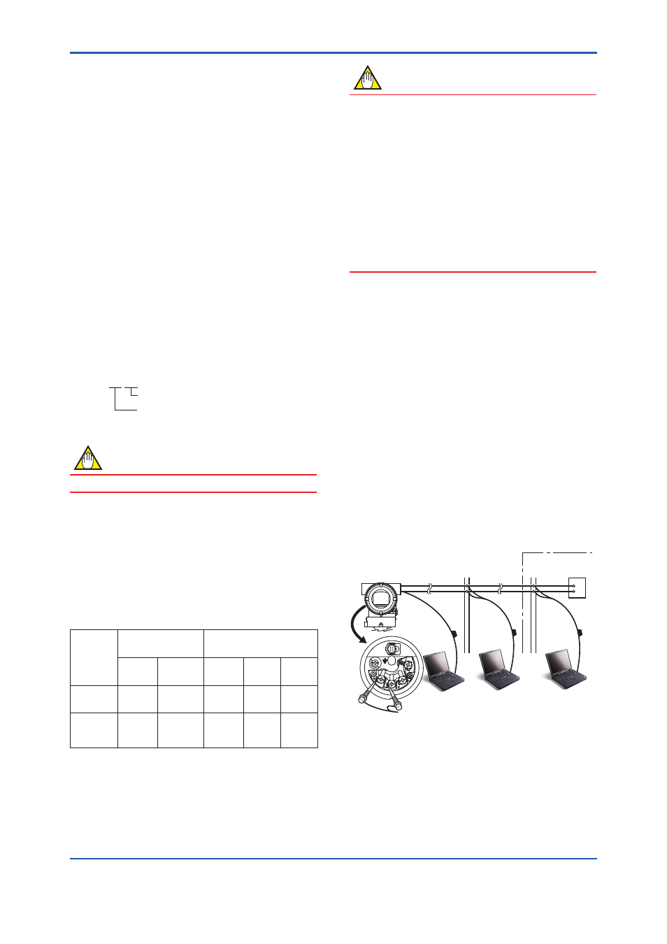
2.5 Interconnection Between
DPharp and the HART
Configuration Tool
The HART configuration tool can interface with the
transmitter from the control room, the transmitter
site, or any other wiring termination point in the
loop, provided there is a minimum of 250 Ω
between the connection and the power supply. To
communicate, it must be connected in parallel with
the transmitter; the connections are non-polarized.
Figure 2.2 illustrates the wiring connections for
direct interface at the transmitter site for the
DPharp. The HART configuration tool can be used
for remote access from any terminal strip as well.
USB
FieldMate
Modem
Relaying
terminals
Distributor
Control room
Terminal
board
F0202.ai
USB
PC/FieldMate
HART configuration tool
DPharp
SUPPL
Y
PULSE
CHECK
ALARM
Figure 2.2
Connecting the HART Configuration
Tool