3 serial interface, 2 performance specifications -4 – Proface GP4100 - 3.4 Compact HMIs" User Manual
Page 35
GP-4100 Series Hardware Manual
3-6
3.1.3
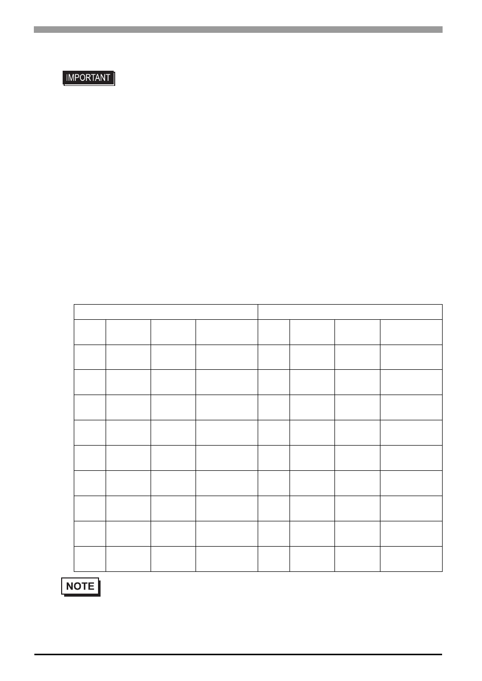
Serial Interface
RS-232C and RS-422/485 Types (GP4105/GP4106)
Included COM I/F connector
(9-pin, 2-piece terminal block)
• For instructions on how to connect to other devices, always refer to the “GP-Pro EX
Device/PLC Connection Manual”.
• The serial interface of the RS-232C and RS-422/485 types is not isolated. Always
connect the SG (Signal Ground) of the GP unit to the connected device, especially if
the connected device is also not isolated. Failure to do so may damage the RS-
232C/RS-422/RS-485 circuit.
• An SG (Signal Ground) and FG (Frame Ground) are connected internally in the RS-
232C and RS-422/485 types. When connecting an external device to the GP using
the SG terminal, be sure to check that no short-circuit loop is created when you
setup the system.
RS-232C type
RS-422/485 type
Label
Signal
Name
Direction
Meaning
Label
Signal
Name
Direction
Meaning
CI
CI(RI)
Input
Called status
display
CSB
CSB
Input
Send
Possible B (-)
CD
CD
Input
Carrier Detect
CSA
CSA
Input
Send
Possible A (+)
CS
CS(CTS)
Input
Send
Possible
ERB
ERB
Output
Data Terminal
Ready B (-)
RS
RS(RTS)
Output
Request to
Send
ERA
ERA
Output
Data Terminal
Ready A (+)
SG
SG
–
Signal
Ground
SG
SG
–
Signal
Ground
DR
DR(DSR)
Input
Data Set
Ready
RDB
RDB
Input
Receive Data
B (-)
ER
ER(DTR)
Output
Data Terminal
Ready
RDA
RDA
Input
Receive Data
A (+)
RD
RD(RXD)
Input
Receive Data
SDB
SDB
Output
Send Data B
(-)
SD
SD(TXD)
Output
Send Data
SDA
SDA
Output
Send Data A
(+)
•
A terminating resistor can be inserted using the DIP Switch (4-bit) on the rear of the RS-422/485
type. Factory default settings are all set to “OFF” (no terminating resistor). Check the terminating
resistor required for connection to the connected device (PLC) and install if necessary. For
detailed information, refer to the GP-Pro EX Device/PLC Connection Manual.