1 gp-4100 series, Chapter 2 part names and functions – Proface GP4100 - 3.4 Compact HMIs" User Manual
Page 27
GP-4100 Series Hardware Manual
2-2
2.1
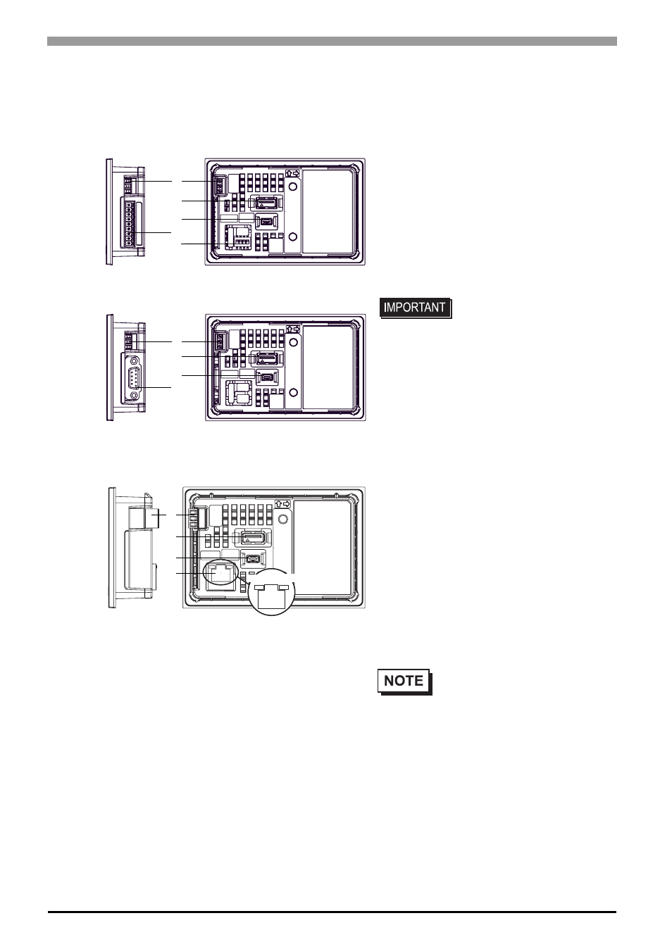
GP-4100 Series
A: Power Connector
B: Serial Interface (COM1)
RS-232C and RS-422/485 Types: 9-pin, 2-piece
terminal block
RS-485(isolation) Type: D-Sub 9 pin (socket)
C: USB (Type A) Interface (USB1)
Complies with USB 2.0, Uses a “TYPE-A”
connector. Power supply voltage: DC5±5%,
The maximum communication distance: 5 m.
D: USB (mini-B) Interface (USB2)
Conforms to USB2.0 (mini-B) x 1
Communication Distance: 5 m or less
E: DIP Switch (SW1)
A terminating resistor can be inserted using the
DIP Switch (4-bit) on the rear of the RS-422/485
type. Factory default settings are all set to “OFF”
(no terminating resistor).
• If connecting a bar code
reader to the GP, be sure
to supply power from an
external source (such as a
self-powered hub). If you
supply power from the GP,
the GP may reset itself
because the GP cannot
supply enough power.
•
Check the terminating resistor
required for connection to the
connected device (PLC) and
install if necessary. For detailed
information, refer to the GP-Pro
EX Device/PLC Connection
Manual.
A
RS-485 (isolation) Type (GP-4107)
C
D
B
E
Right side
Rear
(RS-422/485 Type)
Right side
Rear
A
C
D
B
RS-232C and RS-422/485 Types
(GP-4105, and GP-4106)
Ethernet Type (GP-4104)
A
C
D
F
Right side
Rear
ACT LED
LINK LED