Air cylinder shifter assembly, Blocked clutch – Ramsey Winch RPH-8000 User Manual
Page 11
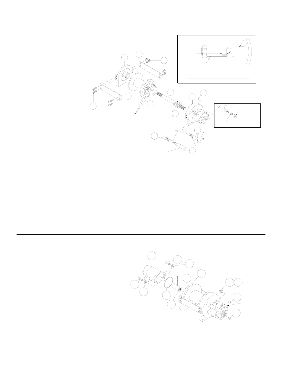
If necessary, remove and replace the shifter assembly (manual, item #2, or air-cylinder, item #3), as follows:
MANUAL CLUTCH SHIFTER ASSEMBLY
Remove by loosening setscrew (item
#25), jam nut and unscrewing clutch
shifter. Be sure slot in ring gear is not
aligned with clutch shifter hole.
Rotate drum, if necessary, to insure
hole and slot are not aligned. Re-install
clutch shifter with plunger, jam nut and
handle positioned in cylinder housing,
as shown. Thread assembly (with
handle engaged in cylinder slot) into
the end bearing. Pull drum toward the
brake housing end bearing to remove
play.
Hold drum in the position and continue
threading the shifter assembly in until
the gap between the end of the handle
and cylinder is 7/16 +0 -1/18 inch
and handle is in the horizontal posi-
tion, as shown below. NOTE: This gap
will vary with drum endplay. With the
drum pulled against the gear housing,
the gap should be 7/16 inch. Lightly
tighten jam nut.
Rotate drum until handle snaps fully into the engaged position. Pull handle out and rotate 90º. Verify that drum can be rotated freely (at least
one full revolution) with clutch shifter at DISENGAGED position. Securely tighten jam nut while holding the handle.
Tighten setscrew securely. Re-check clutch operation as described on Page 5.
AIR CYLINDER SHIFTER ASSEMBLY
Remove by loosening setscrew (item #25), jam nut and unscrewing clutch shifter. To reinstall, thread air cylinder into housing. Install one or
two shims (item #49) under cylinder head, if needed, to orient air cylinder port for pneumatic connections. Tighten setscrew. Refer to Page
5 and check for proper operation of the clutch.
BLOCKED CLUTCH
Insert plunger assembly into gear housing bore so it engages into ring gear slot. Pull drum flange toward gear housing and thread setscrew
into housing until it bottoms out and drum starts to move. Back setscrew out 1/2 turn and lock in place with jam nut.
Before installing motor, check brake adjustment (refer to Page 7, ADJUSTING THE BRAKE).
Place splined end of coupling (item #31), with spirol pin (item
#41) installed, inside of motor end bearing housing (item #7)
and slide over splines on end of input shaft. Place o-ring (item
#38) around motor pilot. Mount motor (item #35) to end
bearing by aligning key on motor shaft with keyway in cou-
pling. Be sure that motor mounts flush to end bearing and that
o-ring is set securely in place between motor and end bearing.
Secure motor to end bearing using two capscrews and lock-
washers (items #24 & #30). Tighten capscrews to 49 ft-lbs.
(66 Nm.). Thread plug (item #40) into bottom of brake hous-
ing. Permatex can be added to threads of plug to help in seal-
ing.
Pour mixture of 1/2 pint (8 ounces) of Mobilfluid 424, Phillips
HG Fluid, Texaco TDH, Shell Oil Company Donax TD high per-
formance tractor transmission fluid, or equivalent, and 1/4 ounce of an oil additive (available from the factory) into oil level hole. Oil level
should be kept at oil level hole (plus or minus 1/8"). Thread plug (item #40) into oil level hole. Insert reducer (item 339) into hole in top of
brake housing and breather plug (item #34) into reducer. Tighten plugs and reducer securely.
11
5
8
7
13
12
18
7/16
-1/16
+0
13
1
CLUTCH SHIFTER
AIR-CYLINDER
PLANET GEARS
PLUNGER
49
3
MANUAL CLUTCH
JAM NUT
2
SHIFTER
MANUAL CLUTCH ADJUSTMENT
HANDLE (HORIZONTAL)
CYLINDER
25
PLUNGER ASSEMBLY
JAM NUT
SETSCREW
BLOCKED CLUTCH
18
OIL LEVEL
40
39
35
24
KEY
7
30
24
31
38
30
41
HOLE
40
34