1 lan connection, 2 serial device connection, Figure 2-27: lan connection – IEI Integration AFL2-W15A-N270 v2.00 User Manual
Page 49
AFL2-W15A-N270 Panel PC
Page 37
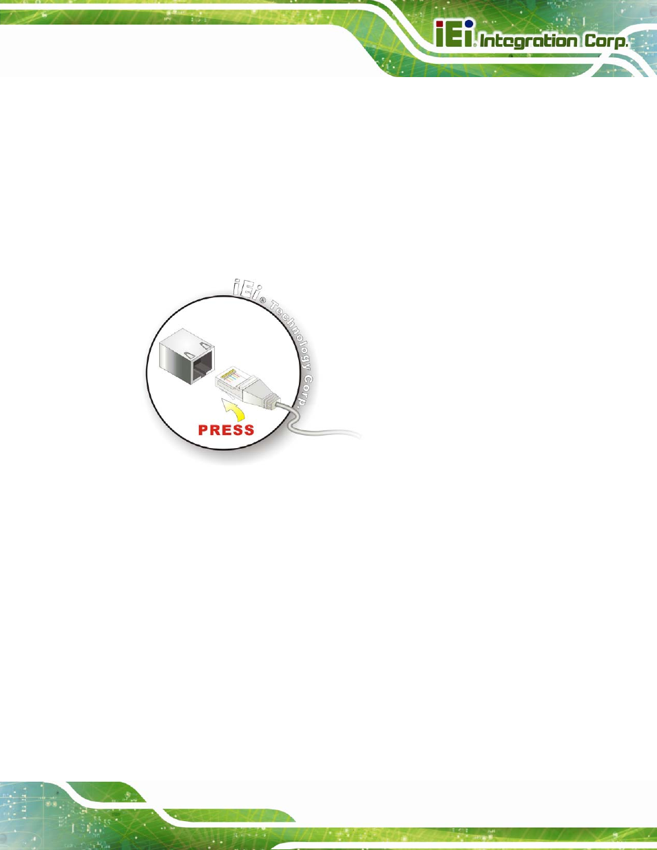
2.9.1 LAN Connection
The RJ-45 connector enables connection to an external network. To connect a LAN cable
with an RJ-45 connector, please follow the instructions below.
Step 1:
Locate the RJ-45 connector
on the bottom panel of the AFL2-W15A-N270.
Step 2:
Align the connectors.
Align the RJ-45 connector on the LAN cable with the
RJ-45 connector on the bottom panel of the AFL2-W15A-N270. See
Figure 2-27: LAN Connection
Step 3:
Insert the LAN cable RJ-45 connector.
Once aligned, gently insert the LAN
cable RJ-45 connector into the onboard RJ-45 port.
Step 0:
2.9.2 Serial Device Connection
The serial device connectors are for connecting serial devices to the AFL2-W15A-N270.
Follow the steps below to connect a serial device to the AFL2-W15A-N270 panel PC.
Step 1:
Locate the DB-9 connector
. The location of the DB-9 connector is shown in
Step 2:
Insert the serial connector
.
Insert the DB-9 connector of a serial device into
the DB-9 connector on the bottom panel. See Figure 2-28.