2 usb connectors, Figure 4-19: rj-45 ethernet connector, Table 4-19: rj-45 ethernet connector leds – IEI Integration ECN-360A-D2550 User Manual
Page 52: Table 4-20: usb port pinouts
ECN-360A-D2550 Em b e d d e d S ys te m
P a g e 41
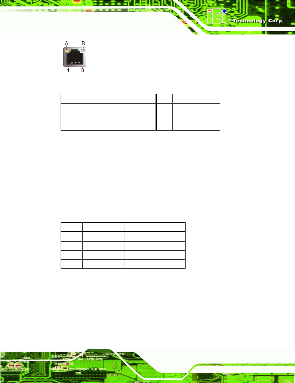
Figure 4-19: RJ-45 Ethernet Connector
LED
Description
LED
Description
A
on: linked
blinking: data is being sent/received
B
off: 10 Mb/s
green: 100 Mb/s
orange: 1000 Mb/s
Table 4-19: RJ-45 Ethernet Connector LEDs
4.3.2 US B Co n n e c to rs
CN La b e l:
US B_CON2, US B_CON3
CN Typ e :
Dual USB 2.0 port
CN Lo c a tio n :
CN P in o u ts :
The ports connect to both USB 2.0 and USB 1.1 devices.
Pin
Description
Pin
Description
1
USB_VCC
2
USB_VCC
3
DATA-
4
DATA-
5
DATA+
6
DATA+
7
GND
8
GND
Table 4-20: USB Port Pinouts
See also other documents in the category IEI Integration Computer Accessories:
- KM-088G (5 pages)
- ECW-281B_D2550 (159 pages)
- ECW-281B_B2-N270 v3.01 (189 pages)
- ECW-281B_B2-N270 v2.00 (180 pages)
- ECW-281B_B2-N270 v2.10 (179 pages)
- ECW-281B_B2-D525 (137 pages)
- IBX-530B-N270 (133 pages)
- uIBX-200-VX800 v1.04 (113 pages)
- uIBX-200-VX800 v2.00 (116 pages)
- uIBX-200-VX800 v2.10 (116 pages)
- uIBX-200 v1.02 (109 pages)
- uIBX-200 v1.10 (113 pages)
- uIBX-210-CV-N2600 (163 pages)
- TANK-101B-D525_N455 v1.02 (119 pages)
- TANK-101B-D525_N455 v1.00 (118 pages)
- TANK-101B-D525_N455 v1.10 (119 pages)
- TANK-800-D525 v1.00 (116 pages)
- TANK-800-D525 v1.14 (137 pages)
- TANK-600-D2550_N2600 (132 pages)
- TANK-GM45A (104 pages)
- TANK-700-QM67 v1.00 (128 pages)
- TANK-700-QM67 v1.12 (145 pages)
- TANK-700-QM67 v2.00 (144 pages)
- TANK-720-Q67 (147 pages)
- TANK-820-H61 v1.00 (158 pages)
- TANK-820-H61 v2.00 (158 pages)
- TANK-820-H61 v2.03 (157 pages)
- TANK-6000-C226 (138 pages)
- IDS-H61 (72 pages)
- IOPS-Q67_H61 (70 pages)
- ECN-680A-H61 (190 pages)
- ECN-780-Q67 (184 pages)
- ECN-360A-HM65 (154 pages)
- EBC-2102 (5 pages)
- ECN-581A-R10-HM551 (6 pages)
- EBC-3200 (6 pages)
- EBC-3100 (8 pages)
- EBC-3000 (7 pages)
- EBC-2100 (4 pages)
- EBC-3620 (8 pages)
- VSTAND (1 page)
- AUPS-C20 v1.01 (49 pages)
- AUPS-C20 v1.02 (55 pages)
- AUPS UART Protocal SPC (11 pages)