3 external interface panel connectors, Table 4-1: peripheral interface connectors, Table 4-2: rear panel connectors – IEI Integration ECN-360A-D2550 User Manual
Page 36
ECN-360A-D2550 Em b e d d e d S ys te m
P a g e 25
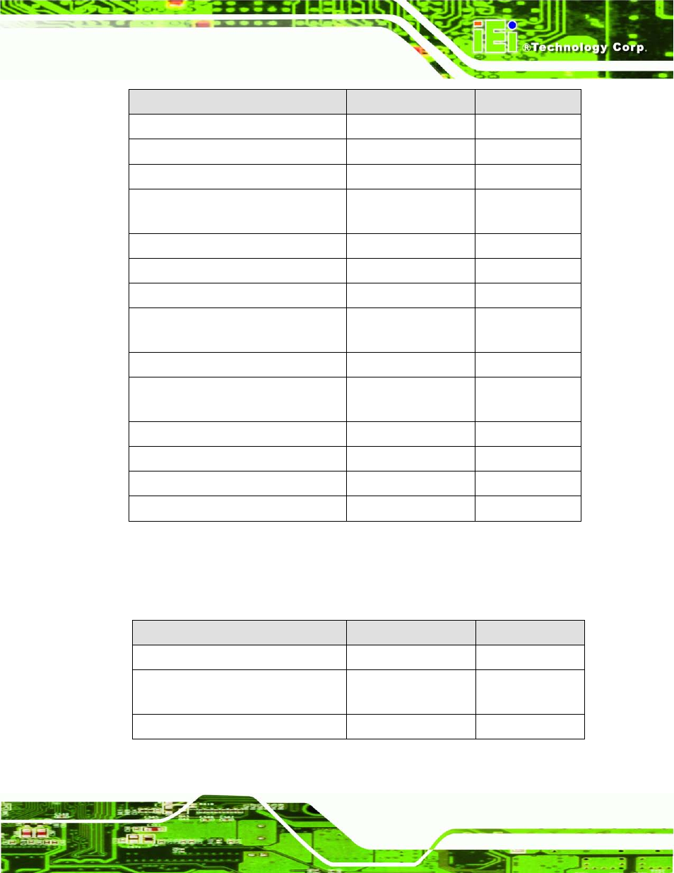
Co n n e c to r
Typ e
La b e l
Backlight inverter connector
5-pin wafer
INV1
Battery connector
2-pin wafer
CN1
Digital Input/Output (DIO) connector
10-pin header
DIO1
Fan connectors
3-pin wafer
CPU_FAN1,
SYS_FAN2
Front panel connector
10-pin header
F_PANEL1
Keyboard and mouse connector
6-pin wafer
KB_MS1
LVDS connector
20-pin crimp
LVDS1
PCIe Mini card slots
52-pin PCIe Mini
M_PCIE1,
M_PCIE2
Power connector (9V~28V)
4-pin connector
CN2
RS-232 serial port connectors
10-pin header
COM1, COM2,
COM3
RS-422/485 serial port connector
4-pin wafer
COM4
Serial ATA (SATA) drive connectors
7-pin SATA
SATA1, SATA2
SO-DIMM connector
SO-DIMM connector
DIMM1
USB 2.0 connector
8-pin header
USB4
Table 4-1: Peripheral Interface Connectors
4.1.3 Exte rn a l In te rfa c e P a n e l Co n n e c to rs
The table below lists the connectors on the external I/O panel.
Co n n e c to r
Typ e
La b e l
Ethernet connectors
RJ-45
LAN1, LAN2
USB connectors
USB 2.0
USB_CON2,
USB_CON3
VGA connectors
15-pin female
VGA1, VGA2
Table 4-2: Rear Panel Connectors