6 fan connectors, Figure 4-7: fan connector locations, Table 4-7: digital i/o connector pinouts – IEI Integration ECN-360A-D2550 User Manual
Page 41: Table 4-8: fan connector pinouts
ECN-360A-D2550 Em b e d d e d S ys te m
P a g e 30
Pin
Description
Pin
Description
3
Output 3
4
Output 2
5
Output 1
6
Output 0
7
Input 3
8
Input 2
9
Input 1
10
Input 0
Table 4-7: Digital I/O Connector Pinouts
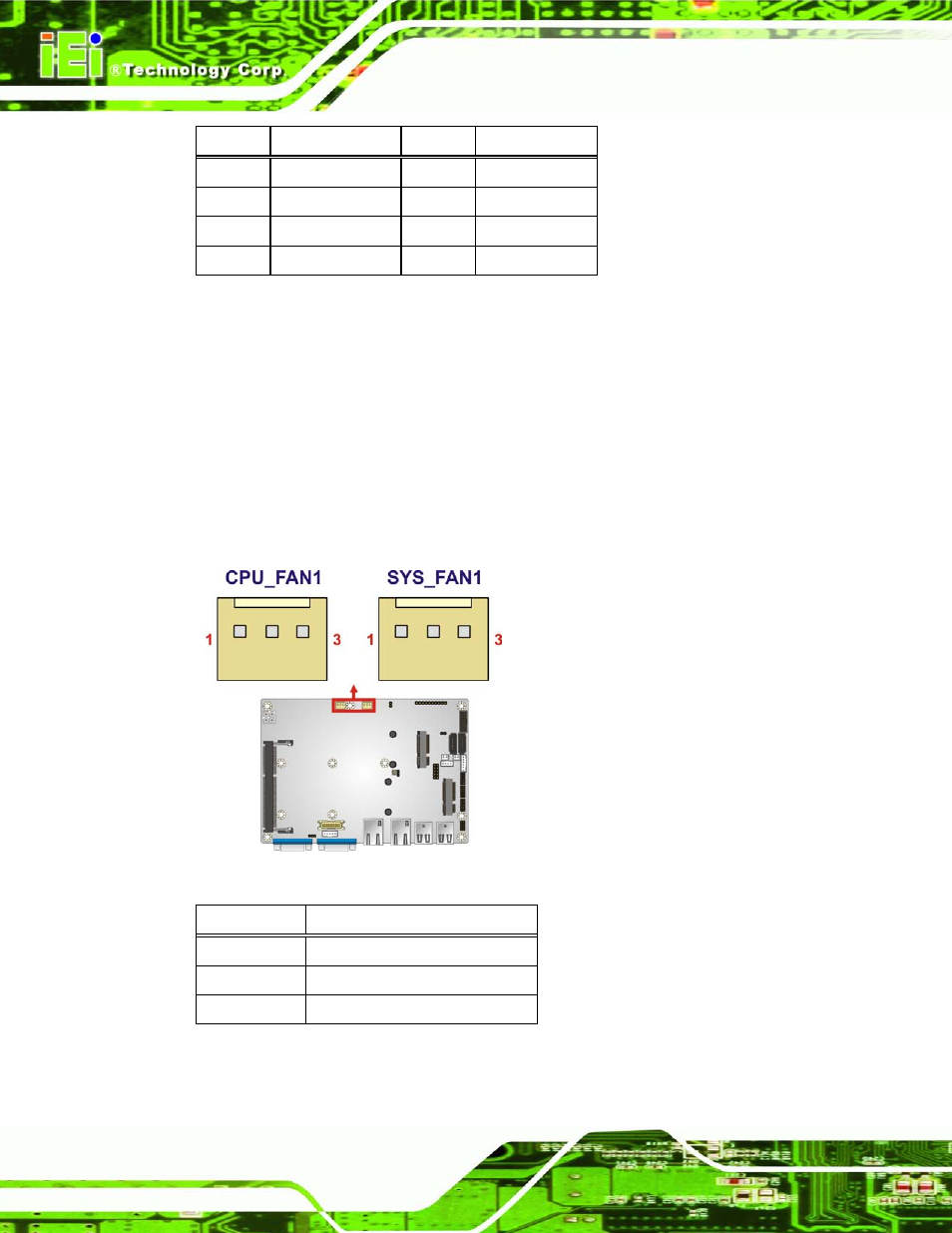
4.2.6 Fa n Co n n e c to rs
CN La b e l:
CP U_FAN1, S YS _FAN1
CN Typ e :
3-pin wafer
CN Lo c a tio n :
CN P in o u ts :
The fan connectors attach to the CPU/system cooling fans.
Figure 4-7: Fan Connector Locations
PIN NO.
DESCRIPTION
1
FANIO
2
+12V (PWM)
3
Ground
Table 4-8: Fan Connector Pinouts
See also other documents in the category IEI Integration Computer Accessories:
- KM-088G (5 pages)
- ECW-281B_D2550 (159 pages)
- ECW-281B_B2-N270 v3.01 (189 pages)
- ECW-281B_B2-N270 v2.00 (180 pages)
- ECW-281B_B2-N270 v2.10 (179 pages)
- ECW-281B_B2-D525 (137 pages)
- IBX-530B-N270 (133 pages)
- uIBX-200-VX800 v1.04 (113 pages)
- uIBX-200-VX800 v2.00 (116 pages)
- uIBX-200-VX800 v2.10 (116 pages)
- uIBX-200 v1.02 (109 pages)
- uIBX-200 v1.10 (113 pages)
- uIBX-210-CV-N2600 (163 pages)
- TANK-101B-D525_N455 v1.02 (119 pages)
- TANK-101B-D525_N455 v1.00 (118 pages)
- TANK-101B-D525_N455 v1.10 (119 pages)
- TANK-800-D525 v1.00 (116 pages)
- TANK-800-D525 v1.14 (137 pages)
- TANK-600-D2550_N2600 (132 pages)
- TANK-GM45A (104 pages)
- TANK-700-QM67 v1.00 (128 pages)
- TANK-700-QM67 v1.12 (145 pages)
- TANK-700-QM67 v2.00 (144 pages)
- TANK-720-Q67 (147 pages)
- TANK-820-H61 v1.00 (158 pages)
- TANK-820-H61 v2.00 (158 pages)
- TANK-820-H61 v2.03 (157 pages)
- TANK-6000-C226 (138 pages)
- IDS-H61 (72 pages)
- IOPS-Q67_H61 (70 pages)
- ECN-680A-H61 (190 pages)
- ECN-780-Q67 (184 pages)
- ECN-360A-HM65 (154 pages)
- EBC-2102 (5 pages)
- ECN-581A-R10-HM551 (6 pages)
- EBC-3200 (6 pages)
- EBC-3100 (8 pages)
- EBC-3000 (7 pages)
- EBC-2100 (4 pages)
- EBC-3620 (8 pages)
- VSTAND (1 page)
- AUPS-C20 v1.01 (49 pages)
- AUPS-C20 v1.02 (55 pages)
- AUPS UART Protocal SPC (11 pages)