Figure 3-20: power input connector, Table 3-6: power input pinouts, Table 3-6 – IEI Integration TANK-700-QM67 v2.00 User Manual
Page 43: Figure 3-20
TANK-700 Em b e d d e d S ys te m
P a g e 31
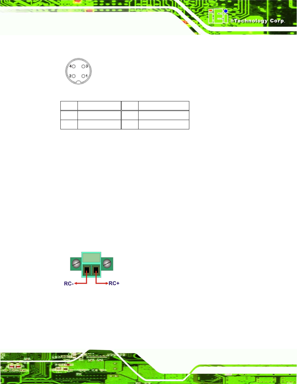
The power connector connects to the 10.5V~36V DC power adapter.
Figure 3-20: Power Input Connector
Pin
Description
Pin
Description
1
+12V
3
+12V
2
GND
4
GND
Table 3-6: Power Input Pinouts
3.9.11 Re m o te Co n tro l Co n n e c to r (Fo r AT P o we r Mo d e On ly)
CN La b e l:
Remoter
CN Typ e :
2-pin terminal block
CN Lo c a tio n :
CN P in o u ts :
The 2-pin terminal block connects to a remote control device. Users can control the
system power on/off by inputting high or low voltage into the terminal block.
Turn off the system: 2 V ~ 5 V input
Turn on the system: less than 0.4 V input
Figure 3-21: Remote Control Terminal Block Pinout Location
See also other documents in the category IEI Integration Computer Accessories:
- KM-088G (5 pages)
- ECW-281B_D2550 (159 pages)
- ECW-281B_B2-N270 v3.01 (189 pages)
- ECW-281B_B2-N270 v2.00 (180 pages)
- ECW-281B_B2-N270 v2.10 (179 pages)
- ECW-281B_B2-D525 (137 pages)
- IBX-530B-N270 (133 pages)
- uIBX-200-VX800 v1.04 (113 pages)
- uIBX-200-VX800 v2.00 (116 pages)
- uIBX-200-VX800 v2.10 (116 pages)
- uIBX-200 v1.02 (109 pages)
- uIBX-200 v1.10 (113 pages)
- uIBX-210-CV-N2600 (163 pages)
- TANK-101B-D525_N455 v1.02 (119 pages)
- TANK-101B-D525_N455 v1.00 (118 pages)
- TANK-101B-D525_N455 v1.10 (119 pages)
- TANK-800-D525 v1.00 (116 pages)
- TANK-800-D525 v1.14 (137 pages)
- TANK-600-D2550_N2600 (132 pages)
- TANK-GM45A (104 pages)
- TANK-700-QM67 v1.00 (128 pages)
- TANK-700-QM67 v1.12 (145 pages)
- TANK-720-Q67 (147 pages)
- TANK-820-H61 v1.00 (158 pages)
- TANK-820-H61 v2.00 (158 pages)
- TANK-820-H61 v2.03 (157 pages)
- TANK-6000-C226 (138 pages)
- IDS-H61 (72 pages)
- IOPS-Q67_H61 (70 pages)
- ECN-680A-H61 (190 pages)
- ECN-780-Q67 (184 pages)
- ECN-360A-HM65 (154 pages)
- ECN-360A-D2550 (141 pages)
- EBC-2102 (5 pages)
- ECN-581A-R10-HM551 (6 pages)
- EBC-3200 (6 pages)
- EBC-3100 (8 pages)
- EBC-3000 (7 pages)
- EBC-2100 (4 pages)
- EBC-3620 (8 pages)
- VSTAND (1 page)
- AUPS-C20 v1.01 (49 pages)
- AUPS-C20 v1.02 (55 pages)
- AUPS UART Protocal SPC (11 pages)