9 power input, 4-pin terminal block, 10 power input, 4-pin din connector, Figure 3-19: 4-pin terminal block pinout location – IEI Integration TANK-700-QM67 v2.00 User Manual
Page 42: Table 3-4: rj-45 ethernet connector leds, Table 3-5: 4-pin terminal block pinouts, 9 p o we r in p u t, 4-p in te rm in a l blo c k
TANK-700 Em b e d d e d S ys te m
P a g e 30
Activity/Link LED
Speed LED
STATUS
DESCRIPTION
STATUS
DESCRIPTION
Off
No link
Off
10 Mbps connection
Yellow
Linked
Green
100 Mbps connection
Blinking
TX/RX activity
Orange
1 Gbps connection
Table 3-4: RJ-45 Ethernet Connector LEDs
3.9.9 P o we r In p u t, 4-p in Te rm in a l Blo c k
CN La b e l:
POWER 1
CN Typ e :
4-pin terminal block
CN Lo c a tio n :
CN P in o u ts :
Connect the leads of a 9V~36V DC power supply into the terminal block. Make sure that
the power and ground wires are attached to the correct sockets of the connector.
Pin
Description
Pin
Description
1
GND
3
Power button
2
VCC
4
ACC
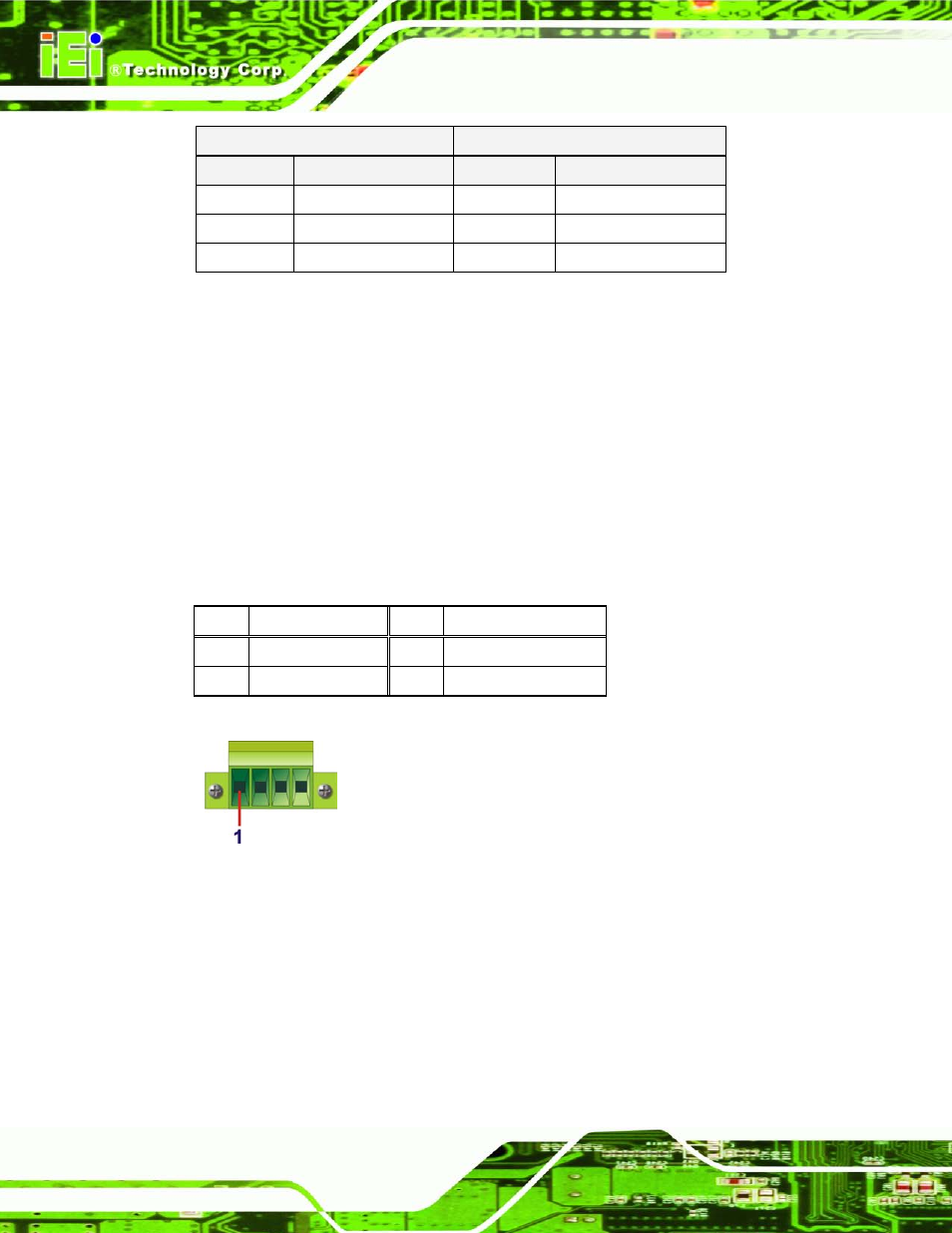
Table 3-5: 4-pin Terminal Block Pinouts
Figure 3-19: 4-pin Terminal Block Pinout Location
3.9.10 P o we r In p u t, 4-p in DIN Co n n e c to r
CN La b e l:
P OWER 2
CN Typ e :
4-pin DIN connector
CN Lo c a tio n : See Figure 1-3
CN P in o u ts :
See Table 3-6 and Figure 3-20