KB Electronics IODA, Input/Output Module for use with all KBDA/KBMK Controls User Manual
Page 9
9
3.1 PREPARING THE DRIVE FOR INSTALLATION OF THE IODA
Use the Allen Key (supplied) to remove the two socket head cap screws located
at the top corners of the KBDA PC board. See Figure 4.
FIGURE 4
PREPARING THE DRIVE FOR INSTALLATION OF THE IODA*
*Model KBDA-24D shown. Layout of Models KBDA-27D, 29, 45, 48 varies slightly.
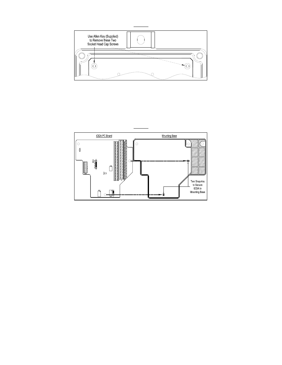
3.3 INSTALLING THE IODA ONTO THE MOUNTING BASE
Use the small mounting base for Model KBDA-24D and the large mounting base
for Models KBDA-27D, 29, 45, 48. Align the IODA PC board holes with the two
snap-ins of the mounting base and press firmly into place until the IODA PC
board is secured onto the mounting base. See Figure 5.
Note: To prevent damage to components press only on the PC board, not on any
components.
FIGURE 5
INSTALLING THE IODA PC BOARD ONTO THE MOUNTING BASE