KB Electronics IODA, Input/Output Module for use with all KBDA/KBMK Controls User Manual
Page 29
29
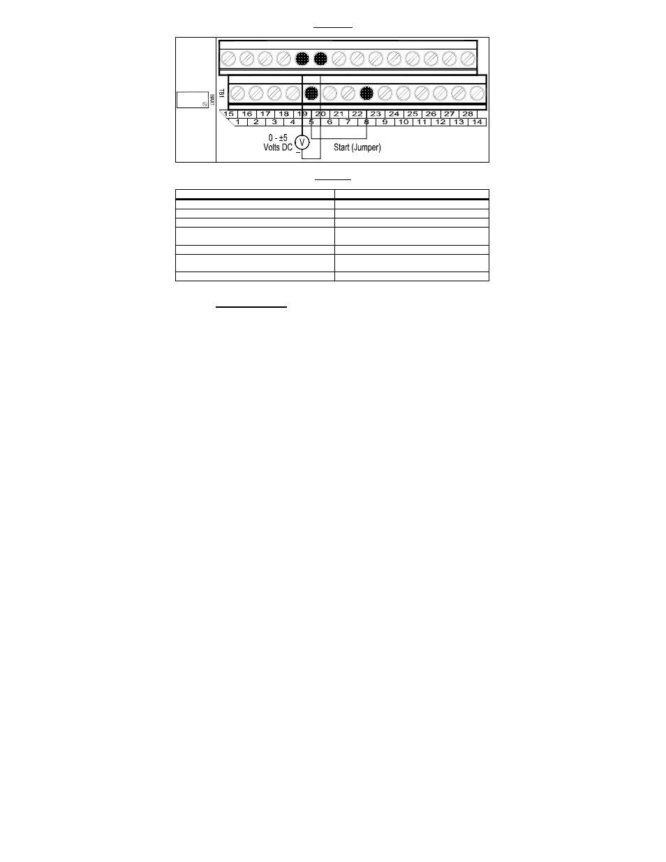
FIGURE 22
ANALOG INPUT "1" SIGNAL VOLTAGE FOLLOWING CONNECTIONS
+
TABLE 15
ANALOG INPUT "1" SIGNAL VOLTAGE FOLLOWING PROGRAMMING
Function No.
Code/Range
2.00: Frequency Control 0002:
Analog Signal 1
9.00: Analog Input 1 Gain 0
–
500:
Set to the Desired Gain
7.04: Multi-Function Input Terminal 5
0010: N.O. Start*
9.01: Analog Input 1 Slope
0000: Positive
0001: Negative
9.02: Analog Input 1 Offset 0
–
100:
Set to the Desired Offset
9.03: Analog Input 1 Type
0000: Unidirectional
0001: Bidirectional
9.04: Analog Input 1 Response Time (mSec) 2 – 100: Set to the Desired Time
*Factory setting.
ANALOG INPUT "2"
See Table 16 for Analog Input 2 electrical ratings.
Voltage Signal Input: Set Jumper J1 to the "VOLT" position (factory setting).
Current Signal Input: Set Jumper J1 to the "CUR" position.
PWM Signal Input: Set Jumper J1 to the "VOLT" position (factory setting).
Connect the signal input to Terminal "21" and the common to Terminal "22".
Connect the Start (Jumper) to Terminal "5", which is factory set for N.O. Start
("0010") and to any available common terminal ("8", "12", "14", "16", "18" "20",
"22"). See Figure 23, on page 30, for connections. See Table 17, on page 30,
for drive programming.
MAX2 Trimpot: If the Analog Input 2 signal voltage is higher than the input
signals specified in Table 16, on page 30, use Trimpot MAX2 to attenuate it.
Apply the maximum signal input and set the drive for full speed output and
observe the display. Rotate Trimpot MAX2 counter clockwise until the drive
output frequency begins to drop. Then rotate Trimpot MAX2 clockwise until the
display returns to the maximum output frequency. Set the signal slope and
adjust the gain, offset, and response time as desired.