KB Electronics IODA, Input/Output Module for use with all KBDA/KBMK Controls User Manual
Page 43
43
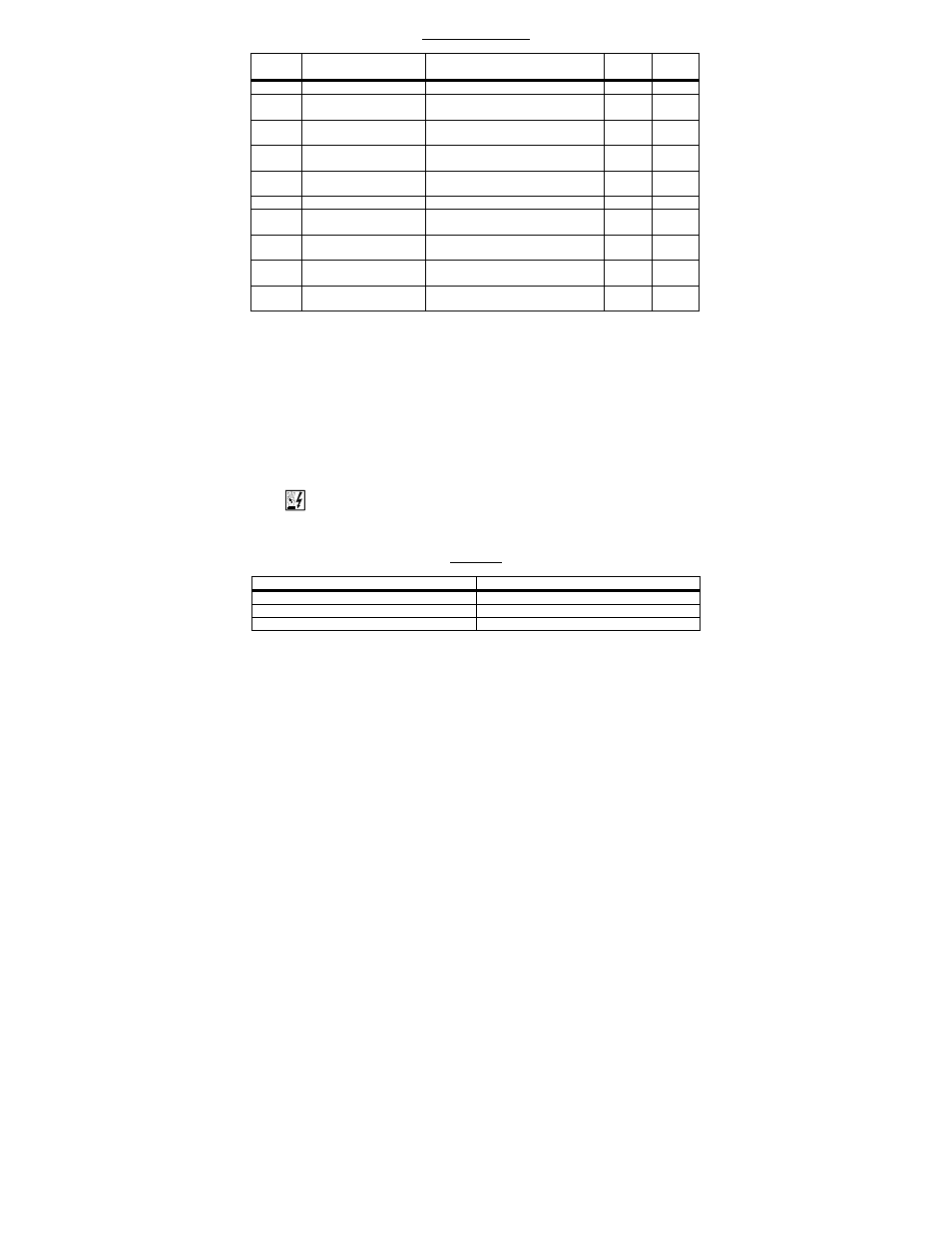
FUNCTION GROUP 9
ANALOG INPUT SIGNAL OPERATION
Function
No. Description
Range/Code
Factory
Setting
Actual
Setting
9.00
Analog Input 1 Gain (%)
1
0 – 500
100
9.01
Analog Input 1 Slope
1
0000: Positive
0001: Negative
0000
9.02
Analog Input 1 Offset
(%)
1
0 – 100
0
9.03
Analog Input 1 Type
1
0000: Unidirectional
0001: Bidirectional
0000
9.04
Analog Input 1
Response Time (mSec)
1
2 – 100
2
9.05
Analog Input 2 Gain (%)
2
0 – 500
100
9.06
Analog Input 2 Slope
2
0000: Positive
0001: Negative
0000
9.07
Analog Input 2 Offset
(%)
2
0 – 100
0
9.08
Analog Input 2 Type
2
0000: Analog Voltage or Current
3
0001: PWM
4
0000
9.09
Analog Input 2
Response Time (mSec)
2
2 – 100
2
Notes: 1. For Analog Input 1 (Function Nos. 9.00 – 9.04), Frequency Control (Function No.
2.00) must be set to Analog Signal 1 (code "0002"). 2. For Analog Input 2 (Function Nos.
9.05 – 9.09), Frequency Control (Function No. 2.00) must be set to Analog Signal 2 (code
"0003). 3. For Current Signal Input, set Jumper J1, on the IODA, to the "CUR" position.
4. 0.15 – 1 kHz (0 – 100% duty cycle).
7 DIAGNOSTIC LEDs
The IODA has two PC board mounted LEDs to provide operational status. The green
power on LED (PWR) indicates that power is applied to the IODA from the drive. The
red status LED (STATUS) provides indication of the IODA operation, as described in
Table 27.
WARNING! Do not depend on the LEDs or the 4-Digit Display to no longer
be illuminated as a guaranteed power off condition. Be sure the main power
switch or circuit breaker is in the "OFF" position before servicing the drive.
TABLE 27
STATUS INDICATOR LED
Condition
Red STATUS LED
Normal Operation
Not Illuminated
Communication Error
1
Flashes 1 Second On and 1 Second Off
Current Source Trip
2
Illuminated
Notes: 1. When a Communication Error occurs, the drive's 4-Digit Display will show "Err4".
2. When a Current Source Trip occurs, the drive's 4-Digit Display will show "CS-t".