KB Electronics IODA, Input/Output Module for use with all KBDA/KBMK Controls User Manual
Page 32
32
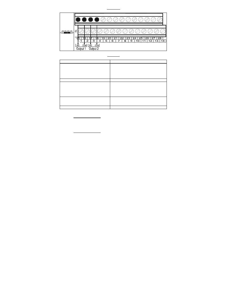
FIGURE 25
ANALOG OUTPUTS "1" AND "2" CONNECTIONS
TABLE 19
ANALOG OUTPUTS "1" AND "2" PROGRAMMING
Function No.
Code/Range
8.06: Analog Output 1 Mode
0000: Motor Frequency
0001: Set Frequency
0002: Motor Voltage
0003: Bus Voltage
0004: Motor Current
8.07: Analog Output 1 Gain 0
–
200:
Set to the Desired Gain
8.08: Analog Output 2 Mode
0000: Motor Frequency
0001: Set Frequency
0002: Motor Voltage
0003: Bus Voltage
0004: Motor Current
8.09: Analog Output 2 Type
0000: 0 – 5 Volts DC
0001: 0 – 20 mA DC
0002: 4 – 20 mA DC
8.10: Analog Output 2 Gain 0
–
200:
Set to the Desired Gain
ANALOG OUTPUT "1"
Connect the auxiliary device signal input to Terminal "15" and the common to
Terminal "16".
ANALOG OUTPUT "2"
Connect the auxiliary device signal input to Terminal "17" and the common to
Terminal "18".
Voltage Signal Output: Set both Jumpers J2 and J3 to the "VOLT" position
(factory setting).
Current Signal Output: Set both Jumpers J2 and J3 to the "CUR" position.