9 motor replacement – IAI America FS User Manual
Page 60
54
5.9 Motor
Replacement
[Items required for the Replacement]
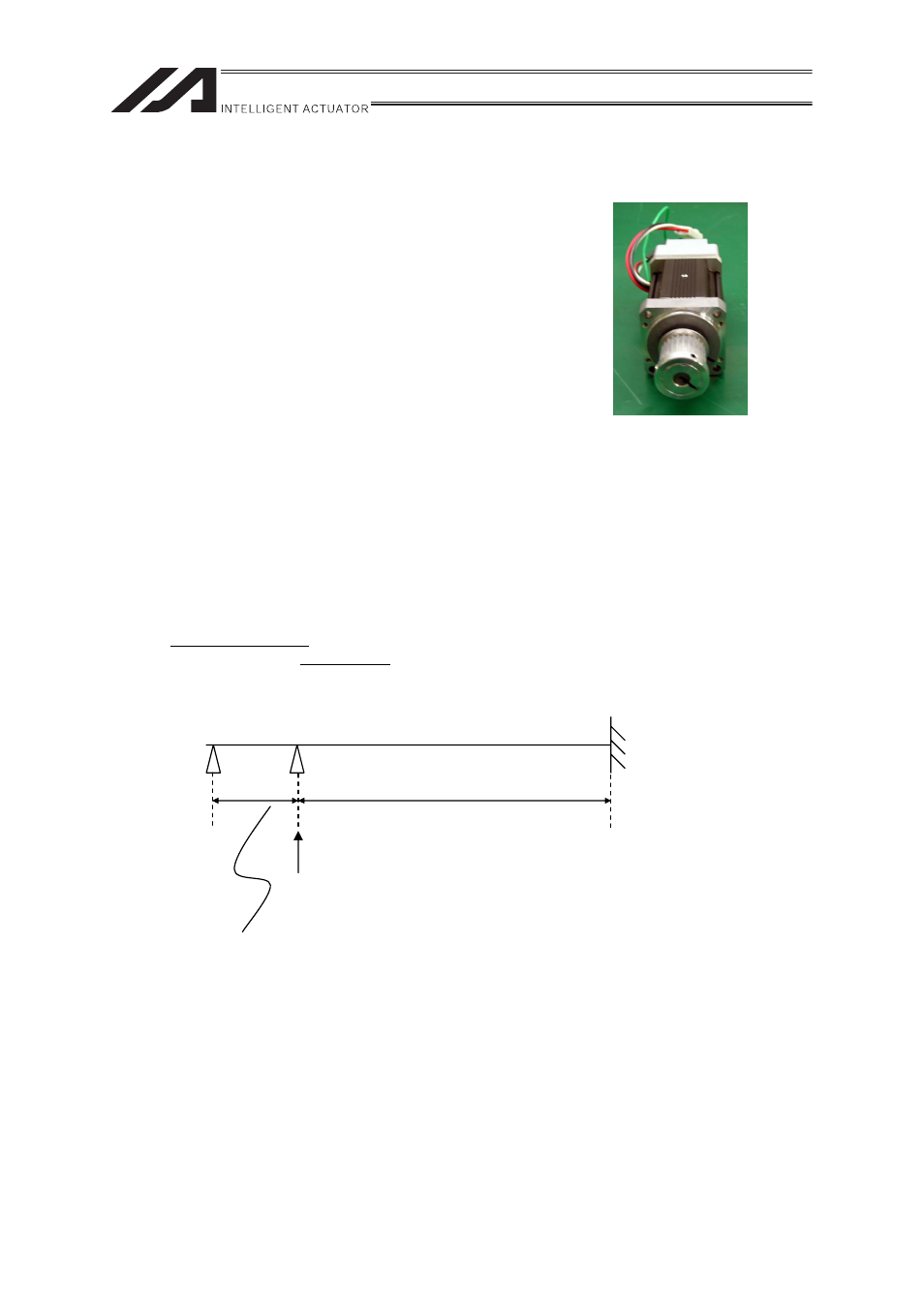
x Replacement Motor (Refer to the picture at right)
(Confirm that the counter mark is attached)
x Hexagon Wrench Set
x Phillips Screwdriver
x Measure
x Personal Computer or Teaching Pendant
x Tension Gauge (Tension of 10kgf or more available)
x Strong Thread (or Long Harness Belt)
[Replacement Operation Outline]
1) Loosen the pulley fixing screw on the driving belt side to detach the deceleration belt, and replace
the motor.
2) Perform the homing operation.
Loosen the deceleration belt, affix the slider at the point of 9mm from the mechanical end on the
home side, and then affix the motor shaft at the alignment mark.
3) Put the deceleration belt and tighten the pulley fixing screw on the driving belt side up to get the
specified tension.
4) Perform a home-return operation with using PC or a teaching pendant to check the amount of
misalignment from the original home position. In case there is misalignment, adjust the position
with Home-Return Offset for E-Con, P-Driver and SCON Controllers. For SSEL Controllers and
X-SEL Controllers, use Home Preset for adjustment.
Mechanical end
NM, WM type
Approx. 9mm
Approx. 1mm
Home Position
At this position, the motor counter mark is aligned.
Z-phase ON position
Establish setting with Home-Return Offset (E-Con, P-Driver and SCON) or Home
Preset (SSEL and X-SEL) in the parameter.