IAI America FS User Manual
Page 31
25
[2] Load
Attachment
x There are M8 tapped holes prepared on the slider. Fix the work piece to be carried.
x The way to affix follows the installation of the main unit.
x There is a restriction on the moment and overhang load length when attaching a load to the
slider.
Type
Allowable
Load
Moment [N•m]
Overhang Load Length [L]
FS-11NM
FS-11NO
Fig. 1)
Single Slider
Ma: 2.9 (0.3)
Mb: 2.9 (0.3)
Mc: 4.5 (0.46)
Ma direction: 200 or less
Mb, Mc direction: 200 or less
FS-12NM
FS-12NO
Fig. 2)
Double Slider
(when sliders are
joined together)
Ma: 20.5 (2.1)
Mb: 18.6 (1.9)
Mc: 9.1 (0.93)
Ma direction: 500 or less
Mb, Mc direction: 500 or less
FS-11WM
FS-11WO
Fig. 1)
Single Slider
Ma: 4.4 (0.45)
Mb: 3.9 (0.4)
Mc: 5.8 (0.6)
Ma direction: 240 or less
Mb, Mc direction: 240 or less
FS-12WM
FS-12WO
Fig. 2)
Double Slider
(when sliders are
joined together)
Ma: 27.4 (2.8)
Mb: 25.4 (2.6)
Mc: 11.7 (1.2)
Ma direction: 600 or less
Mb, Mc direction: 600 or less
FS-11LM
FS-11LO
FS-11HM
Fig. 1)
Single Slider
Ma: 8.8 (0.9)
Mb: 7.8 (0.8)
Mc: 12.7 (1.3)
Ma direction: 300 or less
Mb, Mc direction: 300 or less
FS-12LM
FS-12LO
FS-12HM
Fig. 2)
Double Slider
(when sliders are
joined together)
Ma: 51.9 (5.3)
Mb: 47.0 (4.8)
Mc: 25.4 (2.6)
Ma direction: 750 or less
Mb, Mc direction: 750 or less
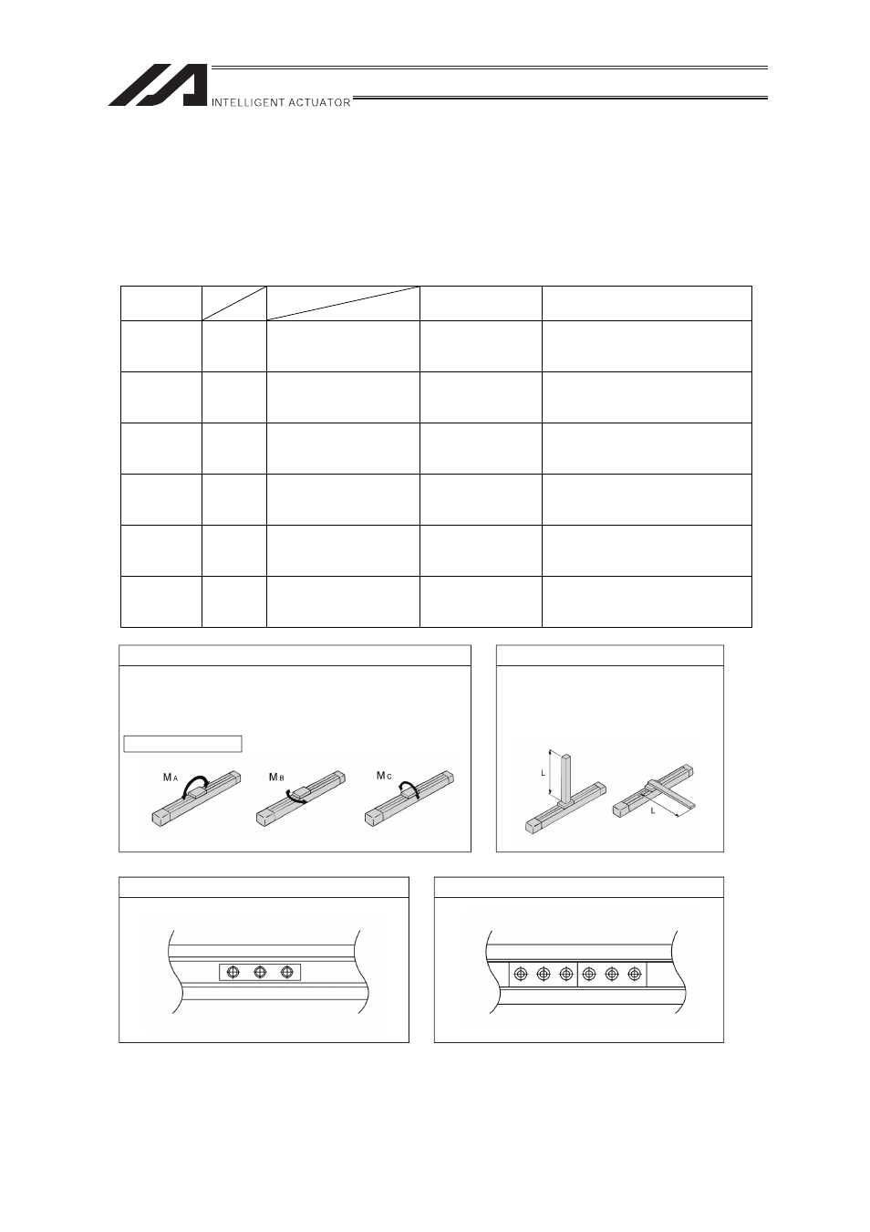
Single Slider (Fig. 1)
Double Slider (Fig. 2)
Allowable dynamic moment directions
The allowable dynamic moment is the value assuming 20,000km.
Use of the actuator above the moment specification could cause
a drop of the life of the guide.
Moment Directions
Overhang Load Length
Use of the actuator with an overhang
above the allowable range for each model
could cause vibration or delay in the
operation time. Make sure to use the
actuator in the allowable range.